


HYDRA
Service Manual
2-32
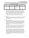
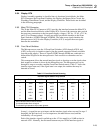
Table 2-8. Display Initialization Modes
A2TP4 A2TP5 Power-Up Display Initialization
1 1 All Segments OFF
1 0 All Segments ON (default)
0 1 Display Test Pattern #1
0 0 Display Test Pattern #2
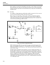
The Display Controller provides 11 grid control outputs and 15 anode control outputs
(only 14 anode control outputs are used). Each of these 26 high-voltage outputs provides
an active driver to the +5V dc supply and a passive 220-kΩ (nominal) pull-down to the -
30V dc supply. These pull-down resistances are internal to the Display Controller.
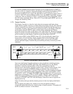
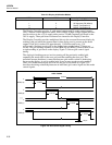
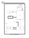
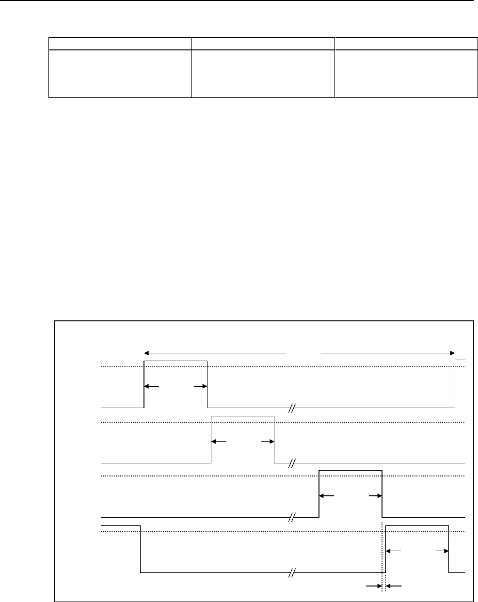
The Display Controller provides multiplexed drive to the vacuum-fluorescent display by
strobing each grid while the segment data for that display area is present on the anode
outputs. Each grid is strobed for approximately 1.14 milliseconds every 13.8
milliseconds, resulting in each grid on the display being strobed about 72 times per
second. The grid strobing sequence is from GRID(10) to GRID(0), which results in left-
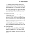
to-right strobing of grid areas on the display. Figure 2-9 shows grid control signal
timing.
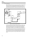
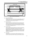
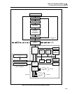
The single grid strobing process involves turning off the previously enabled grid,
outputting the anode data for the next grid, and then enabling the next grid. This
procedure ensures that there is some time between grid strobes so that no shadowing
occurs on the display. A grid is enabled only if one or more anodes are also enabled.
Thus, if all anodes under a grid are to be off, the grid is not turned on. Figure 2-10
describes the timing relationship between an individual grid control signal and the anode
control signals.
1.14 ms
1.14 ms
1.14 ms
1.14 ms
13.8 ms
0V
GRID(10)
0V
GRID(9)
0V
GRID(1)
0V
GRID(0)
…
…
116 µs
GRID TIMING
s9f.eps
Figure 2-9. Grid Control Signal Timing