Performance Testing and Calibration
Performance Tests
4
4-7
1. Ensure that communication parameters (i.e., transmission mode, baud rate, parity,
and echo mode) on Hydra and the host are properly configured to send and receive
serial data. Refer to Section 4 of the Hydra Users Manual.
2. Power up Hydra, and wait 1/2 hour for its temperature to stabilize.
3. Connect a cable from the Output VA HI and LO connectors of the 5700A to the VΩ
and COM connectors on the Hydra front panel.
4. Set the 5700A to output 0V dc.
5. Using either a terminal or a computer running a terminal emulation program as the
selected host, send the following commands to Hydra:
FUNC 0,VDC,I100MV <CR>
MON 1,0 <CR>
MON_VAL? <CR>
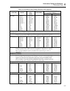
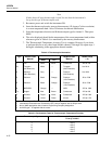
The returned value for channel 0 should be 0 mV ±0.007 mV.
Set the 5700A to output 90 mV DC. Send the following command:
MON_VAL? <CR>
The value returned should now be 90 mV ±0.038 mV (between 89.962 and 90.038
mV).
6. Change the Hydra channel 0 function to the internal 1V dc range by redefining
channel 0. Send the following commands:
MON 0 <CR>
FUNC 0,VDC,I1V <CR>
Set the 5700A to output 0.9V dc. Send the following commands:
MON 1,0 <CR>
MON_VAL? <CR>
The value returned should be 900 mV ±0.22 mV (899.78 to 900.22 mV.)
4-7. 4-Terminal Resistance Test
Verify that the channel 0 accuracy verification tests for dc volts and ohms meet
minimum acceptable levels.
1. Switch OFF power to the instrument and disconnect all high voltage inputs.
2. Remove the Input Module from the rear of the instrument. Open the Input Module
and connect a pair of test leads (keep as short as possible) to the H (high) and L
(low) terminals of channel 1 and a second pair of test leads to the H and L terminals
of channel 11. Reinstall the Input Module into the instrument.
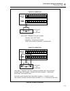
3. Observing polarity, connect the channel 1 test leads to the Sense HI and LO
terminals of the 5700A and the channel 11 test leads to the Output HI and LO
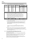
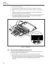
terminals of the 5700A. Route wires with the method shown in Figure 4-1. Connect
the wires to the terminals shown in Figure 4-2.
Note
4-terminal connections are made using pairs of channels. 4-terminal
measurements can be made only on channels 1 through 10. The
accompanying pairs are channels 11 through 20.


