


PRIMERGY BX600 S2 Basic Unit 127
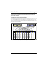
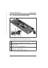
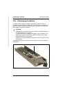
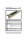
Management Blade Control and Connection Panel
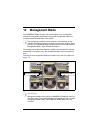
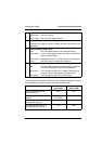
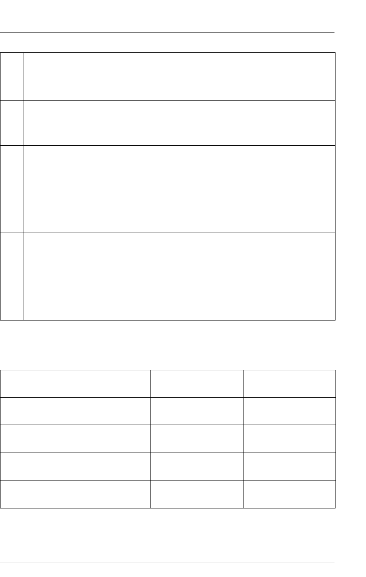
The following table shows the conditions of the management blades indicated
by the interaction of master indicator and failure indicator LEDs.
4 LAN active indicator (amber LED)
Lights amber: The LAN is active.
Blinks amber: Boot up power ready indicator.
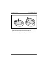
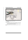
5 I2C connector
Proprietary I2C (IPMI) connector for Fujitsu Siemens Computers service
applications.
6 Failure indicator (amber LED)
Dark: This management blade is OK (see table below).
Lights amber: If only one management blade is present: this blade has
failed (see table below).
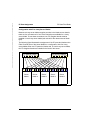
Blinks amber
(2 sec.):
Management blade is running in power up mode (gener-
ating heart beat for master/slave selection).
7 Master indicator (green LED)
Unlit: This management blade is a slave (standby), backup of
the master management blade (see table below).
Lights green: This management blade is the master, responsible for
the entire system management (see table below).
Blinks green: This management blade is in special mode
Management blade condition Master indicator
(green LED)
Failure indicator
(amber LED)
One management blade is
installed and alive
ON OFF
Two management blades are
installed
ON (Master)
OFF (Slave)
OFF
One management blade is
installed and hangs up
ON ON
Two management blades are
installed and both hang up
ON ON