


CHAPTER 2: Getting Started
16
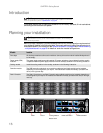
Introduction
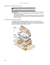
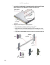
This chapter explains how to install your enclosure into an industry-standard, 19-inch rack cabinet
and configure the enclosure sub-system.
Planning your installation
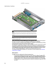
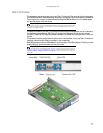
Before you begin installation, you should become familiar with the configuration requirements of
your enclosure, detailed in the following table. The correct positions of each of the optional plug-in
modules are shown in the illustration. See “Ethernet connection” on page 24 and “Enclosure cabling
- multiple enclosures” on page 25 for details of controller module configurations.
Caution
When connecting the enclosure, use only the power cords supplied or cords which
match the specification quoted in “Specifications” on page 29.
Caution
Blank modules or dummy carrier modules MUST be installed in ALL unused bays or
the enclosure may overheat.
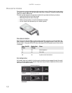
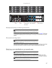
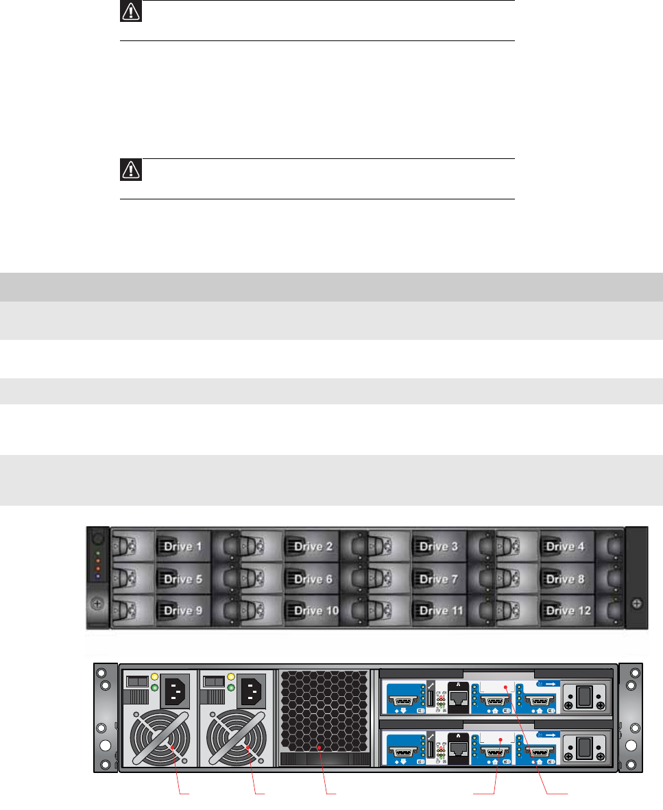
Module Location
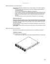
Drive bays All drive bays must have a drive carrier module or dummy drive carrier module installed. No bays should
be left empty.
Power supply (PSU)
modules
Two power supply modules must be installed. Full power redundancy is provided while a faulty module
is replaced. Install the power supply modules in the left rear bays, as shown in the following illustration.
Cooling module Install the cooling module in the rear bay, as shown in the following illustration.
Controller module Two RAID controller modules (or one controller module and one blank module) can be installed,
depending on the configuration you require. The modules are installed horizontally (one above the
other) in the right rear bay.
Disk I/O module Two Disk I/O modules (or one Disk I/O module and one blank module) can be installed, depending on
the configuration you require. The modules are installed horizontally (one above the other) in the right
rear bay.
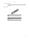
PSU 1 PSU 2 Cooling Module
RAID Controller 1
RAID Controller 0
1
0
1
0
Enclosure module