


www.gateway.com
15
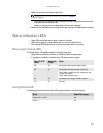
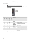
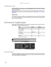
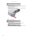
Controller module LEDs
For details on how to remove and replace a controller module see “Controller module” on page 22.
The controller module incorporates the following LED indicators:
* These LEDs blink on and off when there is module activity.
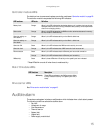
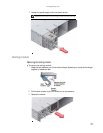
Disk I/O module LEDs
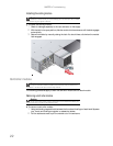
Drive carrier LEDs
See “Drive carrier module faults” on page 16.
Audible alarm
The enclosure subsystem includes an audible alarm which indicates when a fault state is present.
The following conditions activate the audible alarm:
• Fan fault
• Voltage out of range
• Over temperature
• Thermal overrun
• System fault
• Logical fault
• Power supply module fault
LED functions LED state Definition
Battery fault Orange When lit, this LED indicates that the backup battery unit is missing, has low voltage,
has experienced a time-out on charge, indicated a faulty battery, or has experienced
a fault in the charging circuitry.
Cache active Orange When lit, this LED indicates that the RAID controller cache has data saved in memory
but not written to the disk array.
Controller activity on
drive bank 0
Orange When lit, this LED indicates activity on the Bank 0 disk drives.
Controller activity on
drive bank 1
Orange When lit, this LED indicates activity on the Bank 1 disk drives.
Controller OK Green When lit, this LED indicates that RAID controller activity is normal.
Controller fault Orange When lit, this LED indicates that a RAID controller fault has occurred.
Ethernet status Green When lit, this LED indicates that the Ethernet port has a valid connection.
Orange When lit, this LED indicates that the Ethernet port has activity.
SAS activity* Green When lit, these LEDs show I/O activity on the specific port lane indicated.
LED Functions Description
SAS Activity
These LEDs are adjacent to the SAS connectors. When
lit, they indicate I/O activity on a specific port lane (4
lanes).