www.gateway.com
3
• Two plug-in power supply modules, 100-240 V AC, 350 W.
• One plug-in cooling fan module.
• Two plug-in controller modules, each incorporating a RAID controller and a StorView
Management Module.
Enclosure chassis
The chassis consists of a sheet metal enclosure assembly containing a backplane printed circuit
board (PCB) and module runner system.
• The chassis front panel incorporates an integrated operator’s (Ops) panel.
• The backplane PCB provides logic level signal and low voltage power distribution paths.
• The chassis has 19-inch rack mounting features so it fits into a standard 19-inch rack and
uses 2 EIA units of rack space (3.5” high).
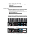
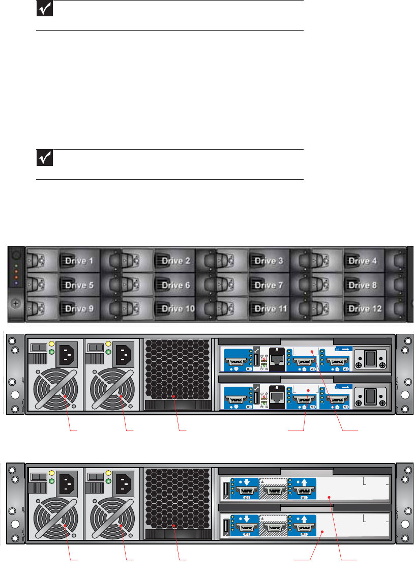
The chassis assembly contains 12 drive bays at the front, each of which accommodates the
appropriate plug-in drive carrier module. The 12 drive bays are arranged in 3 rows of 4 drives per
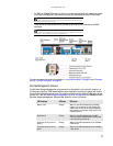
row. In the back, the chassis assembly contains five plug-in module bays to house two power supply
modules (PSUs), a cooling fan module, and two controller modules, which are installed horizontally
(one above the other) in the right bay.
Important
If only one controller module is installed, a blank module must be installed
in the unused slot.
Important
A drive bay is defined as the space required to house a single 1.0" high, 3.5-
inch disk drive in its carrier module.
PSU 1 PSU 2 Cooling Module
RAID Controller 1
RAID Controller 0
1
0
1
0
RAID enclosure (back)
PSU 1 PSU 2 Cooling Module Disk I/O Module 1Disk I/O Module 0
FACTORYUSEONLY
FACTORYUSEONLY
Expansion enclosure (back)


