


154 PMCS Interface Toolkit
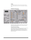
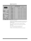
The label color indicates the
function’s availability on the
connected device: gray = not
available, black = available.
Button to enable or disable
the indicated function.
Status indicator: gray = disabled,
amber = enabled.
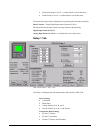
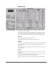
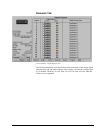
To use this tab, the user selects one of the eight settings groups for editing using the
control labeled "Select Settings Group". The status of the settings in the selected
group will then be displayed, and the user can enable/disable functions without
affecting settings in the other seven groups. Note that the displayed group may not be
the active group currently in use by the relay’s protection algorithms. The
pushbuttons are subject to user level security in Intouch.
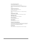
Phase TOC and IOC Settings
The Phase, Neutral, and Ground buttons in this section may be used to select the
display of the TOC and IOC values.
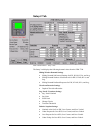
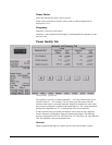
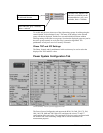
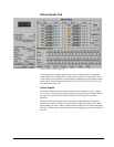
Power System Configuration Tab
Universal Relay - Power System Configuration Tab
The Power System Configuration tab supports the B30, C60, D60, F30, F35, F60,
G60, L60, L90, M60 and T60 UR devices, and shows the source CT and VT
configuration of the entire relay. The supported UR devices can be configured with
one to three DSP cards containing voltage and/or current transformers for
measurement purposes.