


181
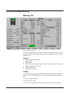
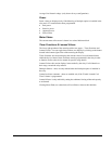
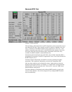
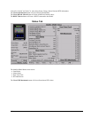
Remote RTD Tab
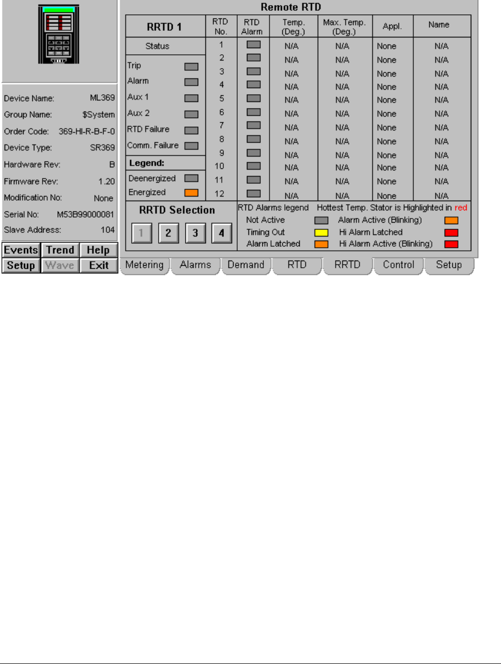
369 Relay - Remote RTD Tab
This tab displays information about any RTD temperature probes connected to one or
more Remote RTD units. These external accessories connect via Modbus to the 369
relay. A maximum of four RRTD modules can be connected to a 369 relay – each
module is assigned a page on this tab. Use the RRTD Selection buttons in the lower
left corner of the tab to navigate between pages. Information on this tab is only
available if an RRTD module is connected to the relay.
Information and alarm indication for each RTD is only available when that RTD is
programmed for operation. If an RTD’s Application is set to "none" then all fields for
that RTD display "N/A".
The hottest Stator RTD indicates which RTD is currently returning the highest
temperature. This condition is indicated by red text in the Temperature field.
Only one alarm condition can be displayed at a time – highest priority alarms are
displayed in the alarm indicator. For example, if a "High Alarm" was triggered and
latched and the RTD value returned to the "Alarm Active" state, the "High Alarm"
latched indicator would persist.
The Status indicators are dedicated to the indicated RRTD module, except for the
Comm. Failure indicator – this will be energized if any configured RRTD module
stops communicating.