


61
Sample Application
Creating a basic interface
We’ve learned about the various parts and pieces of the Interface Toolkit; now let’s
put it to work.
Suppose we have a very basic power management system installed at our corporate
home office. The system consists of four trip units and a PQM (Power Quality
Meter). We’d like to set up a computer in the front office to provide a front end to
this system, allowing us to monitor all these devices at one station without having to
walk back to the individual devices on the plant floor.
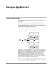
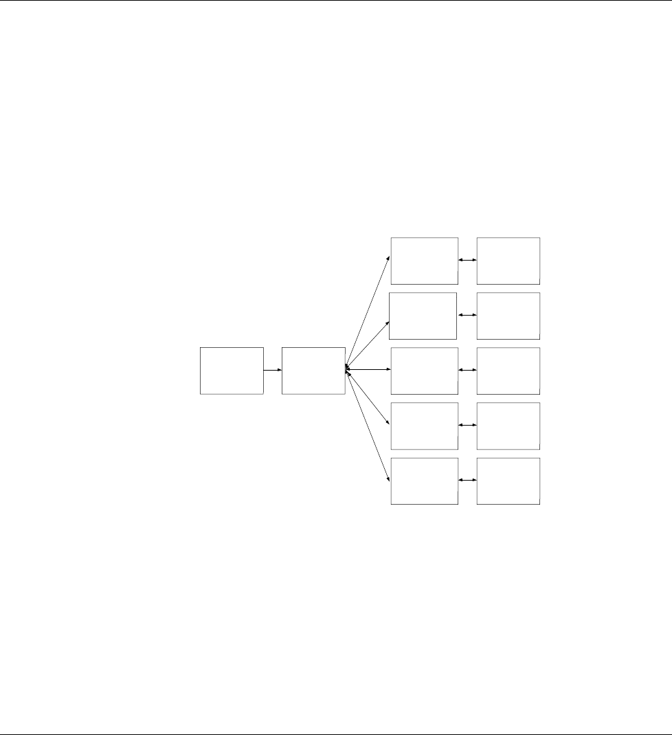
We plan the application on paper first so that we know how many screens to create
and what each screen will look like. This will help us save time when in development
by providing a starting point and a map of what we’re trying to create. This
‘storyboard’ for our application looks something like this:
Intro
screen
Panel
board
PQM
Faceplate
PQM
Tabular
Trip Unit 1
Faceplate
Trip Unit 1
Tabular
Trip Unit 2
Faceplate
Trip Unit 2
Tabular
Trip Unit 3
Faceplate
Trip Unit 3
Tabular
Trip Unit 4
Faceplate
Trip Unit 4
Tabular
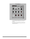
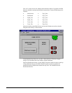
As shown above, for this basic application, we’ll need 12 screens — an introduction
screen, a shot of the panelboard showing all five of our power management devices,
and then a large faceplate and tabular screen for each device. We’ll link the Large
Faceplate screen for each unit to the Small Faceplate wizard shown on the
Panelboard screen, and, from the Large Faceplate, we can click on the device’s
display to jump to the Tabular data screen for that device. To make it easier to
navigate the screens, we’ll create extra buttons on the bottom of the Faceplate and
Tabular screens that will jump back to the Panelboard screen.
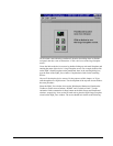
With our plan in hand, and after completing the installation procedures described in
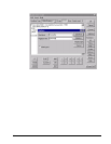
Chapter 1, we’re ready to begin development. Launch InTouch and select the button
to create a new file, then click the Development button.