


238 PMCS Interface Toolkit
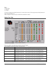
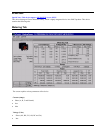
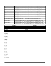
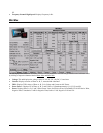
Limit 1 Limit 1 value for the Associated quantity (For example: Phase A Amps)
Trigger - Relay 1 LED display in Amber color : Limit 1 of the associated value will trigger Relay 1.
LED display in Gray color: Limit 1 of the associated value will not trigger Relay 1.
Trigger - Relay 2 LED display in Amber color : Limit 1 of the associated value will trigger Relay 2.
LED display in Gray color: Limit 1 of the associated value will not trigger Relay 2.
Limit 2 Limit 2 value for the Associated quantity (For example: Phase A Amps)
Trigger - Relay 1 LED display in Amber color : Limit 2 of the associated value will trigger Relay 1.
LED display in Gray color: Limit 2 of the associated value will not trigger Relay 1.
Trigger - Relay 2 LED display in Amber color : Limit 2 of the associated value will trigger Relay 2.
LED display in Gray color: Limit 2 of the associated value will not trigger Relay 2.
Set Above/Below Limit 1 LED display in RED color : Limit 1 of the associated value is Set for Above.
LED display in Gray color: Limit 1 of the associated value is Set for Below.
Set Above/Below Limit 2 LED display in RED color : Limit 2 of the associated value is Set for Above.
LED display in Gray color: Limit 2 of the associated value is Set for Below.
Exceeded Limit 1 LED display in GREEN color : The associated quantity is exceeded the Limit 1 value.
LED display in Gray color: The associated quantity is NOT exceeded the Limit 1 value.
Exceeded Limit 2 LED display in GREEN color : The associated quantity is exceeded the Limit 2 value.
LED display in Gray color: The associated quantity is NOT exceeded the Limit 2 value.
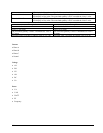
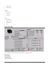
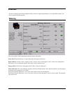
Example 1 Example 2
Limit1 is Set for Above Limit 2 is Set for Below
Limit 1 is 100 Amps Limit 2 is 80 Amps
The associated Quantity is Phase A Instantaneous value is
397 Amps
The associated Quantity is Phase A Instantaneous value is
50 Amps
Exceeded Limit 1 will show in GREEN color as 397>100 Exceeded Limit 1 will show in GREEN color as 50<80
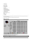
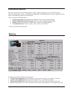
Current
• Phase A
• Phase B
• Phase C
• Neutral
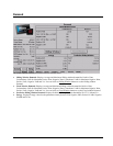
Voltage
• AN
• BN
• CN
• AB
• BC
• CA
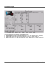
Power
• VA
• VAR
• WATT
• PF
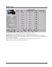
• Frequency