


55
Creating Floor Plans, Elevation
Views, and One-Line Diagrams
Introduction
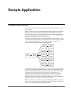
This chapter illustrates how to use the GE wizards described in Chapter 2 to create
animated displays of the facility floor plan, switchgear elevations, and system one-
line diagrams. These examples are typical, but are not intended to display the limits
of creative system design.
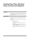
Elevation Views
Elevation views of switchgear and switchboards are typically created first, because
miniature bitmaps of the elevations can be conveniently placed in floor plans as
navigation items.
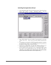
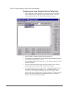
To build an elevation view, place GE Elevation and Small Faceplate wizards into the
window, as follows:
1. Place the appropriate cabinet.
2. Place panels onto the cabinet.
3. Add nameplates, louvers, handles, and fasteners to create the desired
level of detail.
4. Place GE Small Faceplate wizards representing the components
installed in the equipment on top of the elevation wizards, as shown in
the figure on the following page.
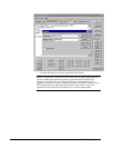
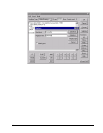
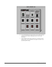
5. Configure each of the Small Faceplate wizards to open a window
containing an appropriate Large Faceplate or Tabular Data Screen for
the device.