


88 PMCS Interface Toolkit
Feature Function
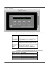
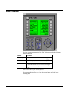
LINE Buttons Rotate among parameters within a page. Certain configurations
or meter values may prevent display of all parameters within a
page. The parameters in each page are listed in the table below.
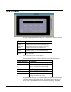
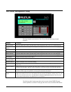
Panel Display
Lights
Display animation that shows the status of the 269 Plus relay. If
a trip or alarm has occurred, auxiliary relay 1 or 2 is active. If the
meter fails its self-test, the dark red square to the left of the label
appears bright red.
Table 10. 269+ Faceplate animated functions.
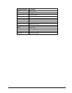
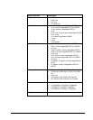
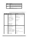
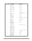
The following table lists the pages that can be accessed with the PAGE buttons, with
the parameters available in each page that can be accessed with the LINE buttons.
Page Value Text Displayed Description
1 PAGE 1: ACTUAL VALUES
PHASE CURRENT DATA
Page header
2 I1=xxx I2=xxx
I3=xxx (AMPS)---
Phase current in amps; --- or RUN based on
motor status
3 I(3 Ph avg.)=xxx AMPS
Max Stator RTD=xxx C
Average phase current
Hottest stator temperature
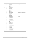
1 4 UNBALANCE RATIO (In/Ip)
U/B=xx PERCENT
5 GROUND FAULT CURRENT
G/F=xxx.0 AMPS
Units = *.1 if G/F CT
ratio = 2000:1
6 ST/HR TIMERS (MIN)
xx xx xx xx xx
Starts per hour
7TIME
BETWEEN STARTS
TIMER = xxx MIN
8 END OF PAGE ONE
ACTUAL VALUES
Page footer
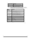
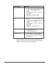
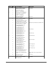
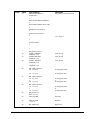
1 PAGE 2: ACTUAL VALUES
RTD TEMPERATURE DATA
Page header
2 HOTTEST STATOR RTD
RTD #xx = xxx
3-12 RTD TEMPERATURE
RTD # xx = xxx
Displays temperatures of RTDs #1-10
2 13 MAX STATOR SINCE LAST
ACCESS: RTD #x = xxx DEGREES C
14-17 MAXIMUM RTD #x TEMP SINCE
LAST ACCESS: xxx DEGREES C
Displays #7-10 max
18 CLEAR LAST ACCESS DATA?
NO
Press STORE to clear; message changes to
YES
19 END OF PAGE TWO
ACTUAL VALUES
Page footer