


249
Limits
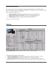
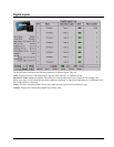
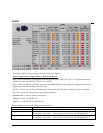
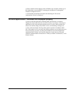
The screen explains various parameters related to Limits and Triggers:
Limit 1 Trigger/Limit 2 Trigger (Relay 1, Relay 2 and Relay 3)
Relay 1, Relay 2 and Relay 3 are triggered depending upon the Limit 1 and Limit 2 values. The screen also displays
whether the Limit 1 and Limit 2 are set above or set below.
Relay 1, Relay 2 and Relay 3 of Limit 1 and Limit 2 are displayed either as Not Triggered or Triggered. If the relay is
triggered, the LED fills with amber, if not then gray.
If Limit 1 or Limit 2 are set above, then the status is displayed in red, if not gray, meaning the Limits are set below,
The Limit 1 and Limit 2 Parameters that are shown on the tab are
Current: Phase A, Phase B, Phase C and Neutral.
Voltage: AN, BN, CN, AB, BC, CA
Power: VA, VAR, WATT, PF and Frequency
Brief explanation of each of the columns is described below
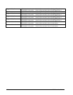
Column Description
Limit 1 Limit 1 value for the Associated quantity (For example: Phase A Amps)
Trigger - Relay 1 LED display in Amber color : Limit 1 of the associated value will trigger Relay 1.
LED display in Gray color: Limit 1 of the associated value will not trigger Relay 1.
Trigger - Relay 2 LED display in Amber color : Limit 1 of the associated value will trigger Relay 2.
LED display in Gray color: Limit 1 of the associated value will not trigger Relay 2.