


57
Floor Plans
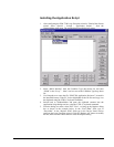
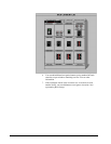
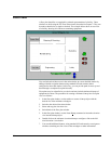
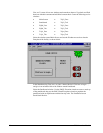
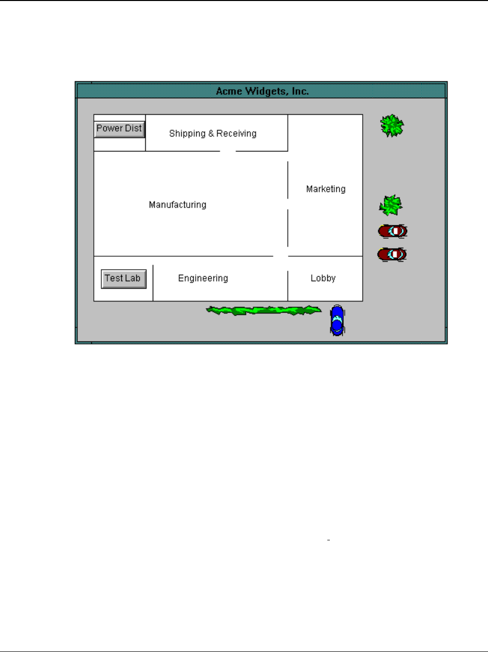
A floor plan should be a recognizable overhead representation of a facility. These
windows are built using the GE Floor Plan wizards, described in Chapter 2. They can
be made as detailed or as simple as desired. The example below shows an overview
of a facility, showing all of the areas containing equipment.
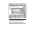
You can link each of these areas in the main window to a more detailed window by
adding a labeled navigation button (using standard InTouch controls) that is
configured to show that window. In this way, you can provide paths to move up and
down through a complete floor plan hierarchy.
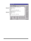
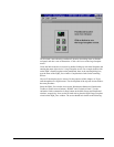
Floor plans may be as detailed as you desire and may include miniature bitmaps of
equipment elevations. The procedure for creating a miniature bitmap in a floor plan
view is as follows:
1. In the floor plan window, use the toolbox to create a bitmap object with the
desired size of the miniature switchgear.
2. Switch to the desired elevation window.
3. Select and copy the elevation view.
4. Switch back to the floor plan window.
5. In the floor plan window, use the Paste Bitmap command to insert the elevation
view into the bitmap object.
6. Double-click on the miniature elevation bitmap to configure a link to the full-
sized elevation view window.
7. You can add additional buttons, using standard InTouch controls, to navigate to
windows containing one-line views of the switchgear or other information.