


230 PMCS Interface Toolkit
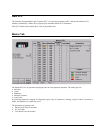
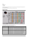
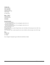
Reset
• WATT Hour
• VAR Hour
• VA Hour
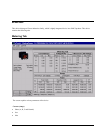
If it is kilo volt inputs, the decimal placement is 2 (as shown in the screen); if kilo amp input the decimal placement is 3
and if mega watt input, it is 1.
Note: Configured is displayed in green, Enabled in red and Reset in Amber.
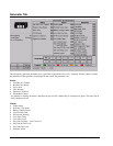
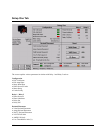
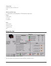
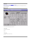
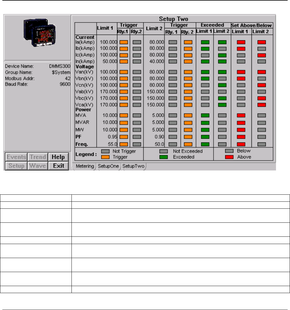
Setup Two Tab
The screen explains various parameters related to Limits and Triggers:
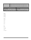
Brief explanation of each of the columns is described below
Column Description
Limit 1 Limit 1 value for the Associated quantity (For example: Phase A Amps)
Trigger - Relay 1 LED display in Amber color : Limit 1 of the associated value will trigger Relay 1.
LED display in Gray color: Limit 1 of the associated value will not trigger Relay 1.
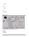
Trigger - Relay 2 LED display in Amber color : Limit 1 of the associated value will trigger Relay 2.
LED display in Gray color: Limit 1 of the associated value will not trigger Relay 2.
Limit 2 Limit 2 value for the Associated quantity (For example: Phase A Amps)
Trigger - Relay 1 LED display in Amber color : Limit 2 of the associated value will trigger Relay 1.
LED display in Gray color: Limit 2 of the associated value will not trigger Relay 1.
Trigger - Relay 2 LED display in Amber color : Limit 2 of the associated value will trigger Relay 2.
LED display in Gray color: Limit 2 of the associated value will not trigger Relay 2.
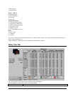
Set Above/Below Limit 1 LED display in RED color : Limit 1 of the associated value is Set for Above.
LED display in Gray color: Limit 1 of the associated value is Set for Below.
Set Above/Below Limit 2 LED display in RED color : Limit 2 of the associated value is Set for Above.