


58 PMCS Interface Toolkit
Electrical One-Line Diagrams
One-line diagrams are built by placing and linking circuit elements using the One-
Line wizards, then creating scripts to provide animation for those wizards whose
status can be determined or controlled, such as breakers and switches.
A one-line diagram is drawn by placing GE One-Line wizards into a window. All
animated One-Line wizards have at least one discrete tag to indicate the status of the
bus feed to the device, while others may have tags for in and out connections and for
device status. If you do not require animation, link the wizard’s discrete tags to a
constant tag with a value of true.
After the device wizards have been placed and configured, they may be connected by
standard InTouch line graphics. Double-click on lines to configure them for
animation. You can link a line to a discrete variable, with the colors set to indicate on
(typically green) and off (typically red). If several lines are used to indicate one
section of bus, animate them together with the Make Symbol toolbox selection.
When a one-line diagram is too large to comfortably fit into a single window, place
navigation buttons with links to other windows near each bus line that continues to
another screen. This allows intuitive navigation up and down a distribution system
hierarchy.
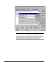
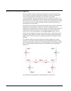
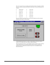
To accurately animate your one-line diagram once all the graphics are in place,
condition scripts must be written with the logic for the distribution system. See the
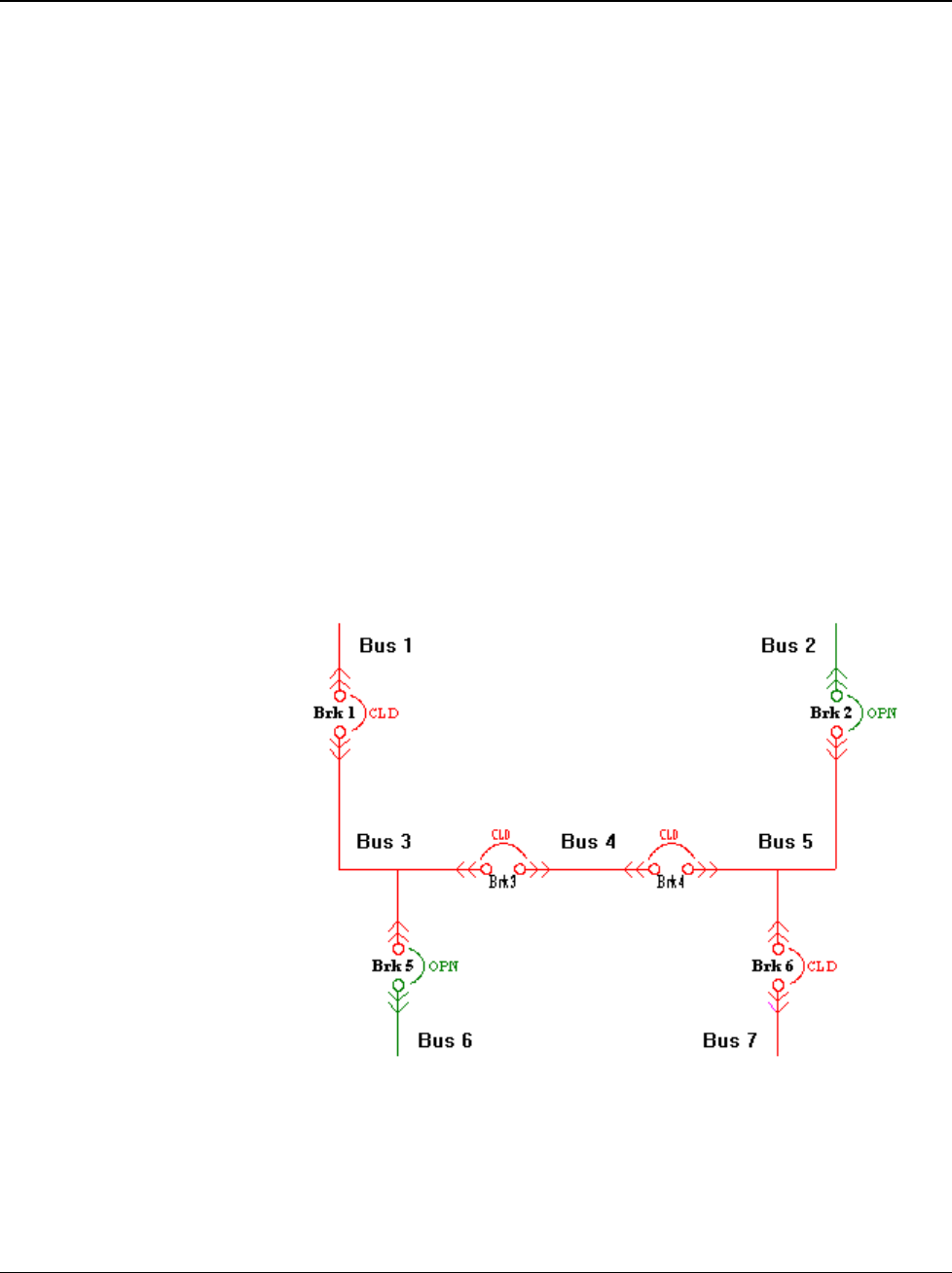
InTouch documentation for details of the scripting language. The following example
shows a simple double-ended substation with a tie breaker and the scripting that
animates it.
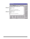
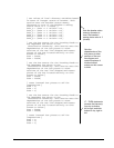
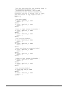
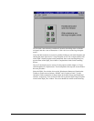
An example of the scripting for this one-line diagram is shown below: