


GFK-1541B Chapter 3 Programming Channel Commands 3-35
3
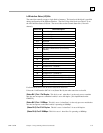
Each SRTP channel has a dedicated pair of bits as follows:
(Status Bits 17, 19, 21 ... 79) Data Transfer Bit:
This bit is normally set to 0. It is pulsed to 1
and back to 0 on successive PLC scans each time a transfer completes successfully.
Do not
assume that when the Data Transfer bit goes to 1 that a transfer has just completed during the
last scan
. The Data Transfer bit is not closely synchronized in time with the transfer. The bit
only indicates that a transfer has occurred during the preceding read (or write) period. A rising
edge on the Data Transfer bit indicating that a transfer has completed successfully does not
guarantee that the next transfer has not begun or completed. In the case of an Establish Channel
command, the CRS word is always updated
before
the Data Transfer bit is set to 1.
(Status Bits 18, 20, 22 ... 80) Channel Error Bit:
This bit is set to 1 when an error is detected on
this channel. It is set to 0 when the channel is initially established and if the channel resumes
normal operation after a transient error condition subsides. The Channel Error bit is also set to 0
when the channel is aborted by an Abort Channel command or when the PLC CPU transitions
from RUN to STOP. In the case of an Establish Channel command, the CRS word is always
updated
before
the Channel Error bit is set to 1.
Note
For Series 90-30 PLCs, bits 49-80 are reserved for future use.