


GFK-1541B Chapter 5 Ethernet Global Data 5-17
5
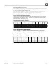
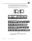
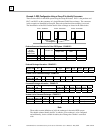
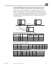
Example 1: EGD Configuration Using IP Addresses to Identify Consumers
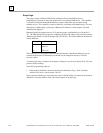
There are two PLCs in this simple EGD system. PLC1 is the producer and PLC2 is the consumer
of a single Ethernet Global Data exchange. The consumer in this example is identified by IP
address. Network-synchronized time stamping is not used. The identification of the PLCs and
the details of the exchange are shown in the tables below.
PLC1 - Producer PLC2 - Consumer
P
C
Exchange
Producer/Consumer Information for Entire EGD System – EXAMPLE 1
Ethernet Interface(s)Your Name for
the PLC
(Equipment
Folder Name)
PC Local
Producer ID
Network
Adapter Name
CCU Device
Name
IP Address*
PLC1 X 0.0.0.1 PLC1 PLC1 10.0.0.23
PLC2 X 0.0.0.2 PLC2 PLC2 10.0.0.41
P=Producer C=Consumer * Use your own IP addresses here.
Produced Exchange Information – EXAMPLE 1
Local
Producer ID
Exchange
ID
Local Adapter Name Consumer
Type
Consumer
Address
Send
Type
Producer
Period
Reply
Rate
Status
Word
0.0.0.1 1 PLC1 IP Address 10.0.0.41 Always 1000 N/A Stat1
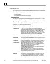
Variable List for Produced Exchange – EXAMPLE 1
Local
Producer ID
Exchange
ID
Var
#
Name Address Length Type Description
0.0.0.1 1 1 Conveyor1 %R00100 5 WORD Conveyor 1 in PLC1
Consumed Exchange Information – EXAMPLE 1
Local
Producer ID
Exchange
ID
Local Adapter Name Remote
Producer ID
Group
ID
Consumer
Period
Update
Timeout
Status
Word
Time
Stamp
0.0.0.2 1 PLC2 0.0.0.1 0 1000 2000 Stat1 n/a
Variable List for Consumed Exchange – EXAMPLE 1
Local
Producer ID
Remote
Producer ID
Exchange
ID
Var
#
Name Address Length Type Description
0.0.0.2 0.0.0.1 1 1 Conveyor1 %R00200 5 WORD Conveyor 1 from PLC1
Note
These tables contain definitions of ALL the exchanges in the entire EGD
system. The shaded columns identify the PLC in which a given exchange is to
be configured and additionally, for the variable list tables, the exchange the
variable is associated with.