


GFK-1541B E-1
Translating PLC CPU Reference Addresses to
Modbus Register Addresses for the
IC693CMM321
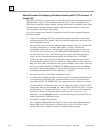
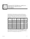
The Modbus/TCP protocol defines operations on a set of reference tables (Register, Input
Register, Input Discrete, and Coil); these Modbus tables differ from the PLC reference tables
within the PLC CPU (%I, %AI, %Q, %AQ, %M, and %R). To implement the Modbus/TCP
protocol, the IC693CMM321 maps each of the Modbus tables into one or more PLC CPU tables
(see Table below). The IC693CMM321 makes no distinction between the Register and Input
Register tables.
IC693CMM321
Internal Tables
Modbus Register
Table
(4xxxxx)
Modbus Input
Register Table
(3xxxxx)
Modbus Input
Discrete Table
(1xxxx)
Modbus Coil
Table
(0xxxx)
%I1 – 4096
(bits)
1 – 256
(16-bit words)
1 – 256
(16-bit words)
1 – 4096
(bits)
---
%AI1 – 16384
(16-bit words)
257 – 16640
(16-bit words)
257 – 16640
(16-bit words)
--- ---
%Q1 – 4096
(bits)
16641 – 16896
(16-bit words)
16641 – 16896
(16-bit words)
--- 1 – 4096
(bits)
%AQ1 – 12288
(16-bit words)
16897 – 29184
(16-bit words)
16897 – 29184
(16-bit words)
--- ---
%R1 – 32640
(16-bit words)
29185 – 61824
(16-bit words)
29185 – 61824
(16-bit words)
--- ---
%M1 – 4096
(bits)
61825 – 62080
(16-bit words)
61825 – 62080
(16-bit words)
--- ---
Mapping Code
(16-bit word)
65535
(16-bit word)
65535
(16-bit word)
--- ---
Table E-1 - Modbus Register / IC693CMM321 Reference Table Translation
Note: The Mapping Code is a read-only address. A client may read this address to determine the
mapping in use without knowing what type of device this is. The IC693CMM321 will return a 1
when this register is read, indicating that the above mapping in is use.
E
Appendix