


7-4 TCP/IP Ethernet Communications for the Series 90™ PLC User's Manual
–
May 2002 GFK-1541B
7
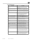
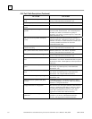
PLC Fault Table
The PLC Fault Table can be accessed in PLC programming software. If you are experiencing a
problem with the Ethernet Interface, check the PLC Fault Table for a fault message, then refer to
the table that follows in this chapter for instructions on what to do about the problem.
To access the details of a PLC Fault Table entry:
For Windows-based PLC programming software, double-click the Fault Table entry and the
details are displayed as “fault extra data”. Refer to Online Help in the PLC programming
software for more information.
For Logicmaster 90 programming software, select the Fault Table entry and press <CTRL-F>
to view the fault details. The “fault extra data” are the long strings of digits on the right half
of the message line. Refer to GFK-0265,
Logicmaster 90-70 Programming Software
Reference Manual
or GFK-0467,
Series 90-30/20/Micro Programming Software Reference
Manual
, for more information.
An example of the fault extra data is shown below:
For Ethernet Interfaces the leftmost 14 digits of fault extra data (underlined in the example above)
show the corresponding log Events (2 digits) and Entries 2, 3, and 4 (in that order, 4 digits each).
The example above is reporting an Event 16, Entry 2=6, Entry 3=3, and Entry 4=5.
This information can be used to refer directly to detailed fault descriptions included in the Log
event table under the LOG command in GFK-1186,
TCP/IP Ethernet Communications for the
Series 90 PLC Station Manager Manual
.
160006000300050000000000000000000000000000000000