


3-18 TCP/IP Ethernet Communications for the Series 90™ PLC User's Manual
–
May 2002 GFK-1541B
3
Status word. If the channel number is the same as a channel already in use, the channel will be
re-tasked to perform this new command.
(Word 9) Number of Write Repetitions:
Word 9 specifies the number of writes to be performed
before automatically completing the communications request and closing the channel. If this
value is set to 1, only a single write will be issued. If this value is set to 0, writes will be issued on
the requested period until the channel is aborted.
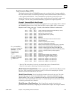
(Word 10) Time Units for Write Period:
Words 10–11 together define how often the write is to
be performed (
write period
). Word 10 specifies the time unit such as seconds or minutes for the
write period. Word 11 specifies the number of those units. The choices for the time units are :
Value Meaning
1 hundredths of seconds (10 ms)
2 tenths of seconds (100 ms)
3 seconds
4 minutes
5 hours
(Word 11) Number of Time Units for Write Period:
Word 11 specifies the number of time units
for the write period. The write period is in effect even when the Channel command is setup to
issue a single write.
Example Write Period Calculation:
If Word 10 contains a value of 3 specifying seconds as the
time unit and Word 11 contains a value of 20, then the write period is 20 seconds.
A write will normally be issued at the start of each write period. If the
pending
write transfer has
not completed during the write period, the Channel Error bit and Detailed Channel Status words
will be set to indicate a non-fatal period error. The pending transfer can still complete after the
period error occurs. For Channel commands set up to issue multiple writes, the next write
transfer will be issued only after the pending write transfer completes
.
If the Number of Time Units is zero, a subsequent transfer will be issued as soon as the previous
transfer completes. In this case, no period errors are reported by the Channel Error bit.
(Word 12) Timeout for Each Write:
Word 12 specifies the time (in hundredths of a second) the
Ethernet Interface will wait for a write transfer to complete before setting the Channel Error bit
and Detailed Channel Status bits to indicate a non-fatal timeout error. The transfer can still
complete even after a timeout occurs. As a result, an application can choose what to do if one
occurs. If the timeout value is specified as zero, no timeout errors will be reported.
For most applications a timeout need not be specified because the write period, in effect, acts as a
timeout. (Word 12 should be zero for no timeout.) However, there are two special
circumstances in which specifying a timeout is recommended:
When the number of time units (Word 11) is zero, so that a subsequent transfer will be issued
as soon as the previous transfer completes and no period errors are reported. In this case a
timeout value can be specified so that timeout errors will be reported by the Channel Error
bit.
When the write period is very long (minutes or hours). In this case a shorter timeout value
can be specified so the application doesn’t have to wait for the write period to expire before
taking action.
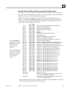
(Word 13) Local PLC - Memory Type:
Words 13–14 specify the location in the local PLC from
where the Ethernet Interface will get the data to be written to the remote PLC. Valid values for
Word 13 are listed in the description of Establish Read Channel. The amount of data to be
A Channel
command set up to
issue a single write
can have only one
pending
write
transfer.