


GFK-1541B Chapter 2 Installation 2-41
2
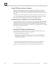
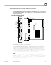
Installing the IC697CMM742 Ethernet Interface
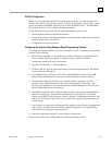
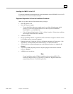
The IC697CMM742 Ethernet Interface is mounted in a Series 90-70 PLC rack. It is connected to
an Ethernet network via a 10Base-T port, a 10Base2 port, or a user-provided transceiver cable and
transceiver via an AUI port.
IC697CMM742 Ethernet Interface
ETHERNET
INTERFACE
MODULE OK
LAN ONLINE
SERIAL ACTIVE
STATUS
RESTART
STATION
MGR
RS
232
SERVICE
OPTION
S/W
LOAD
RS
485
C
O
N
N
E
C
T
I
O
N
10
BASE
T
10
BASE
2
OR
AUI
OR
E
T
H
E
R
N
E
T
S
E
R
I
A
L
S
C
O
N
N
E
C
T
I
O
N
DEFAULT STATION ADDRESS
LABEL
FU3
JP7
LEDS
RESTART
PUSHBUTTON
STATION MGR (RS-232)
SERIAL PORT
SERVICE OPTION
CONNECTOR
S
OFTWARE LOAD (RS-485)
SERIAL PORT
10BaseT NETWORK
PORT
AUI NETWORK PORT
10Base2 NETWORK
PORT
DISABLE ONBOARD
10Base2 PORT JUMPER
REPLACEABLE FUSE
a45598
SERIAL
NUMBER
LABEL
The CMM742 has several user-accessible elements.
Four LEDs are located at the top of the board. The Restart pushbutton is located immediately
below the LEDs. The RS-232 serial port with the RJ-11 connector (similar to a modular
telephone connector) is the Station Manager port. The RS-485 serial port with the 15-pin “D”
connector located immediately below the Station Manager port is the module’s Software Loader
port. Below these there are three ports, any one of which can be used to connect to the Ethernet
network: the 10Base-T, RJ-45 port, the AUI port, and the 10Base2, BNC port.
LEDs
There are four LEDs on the Ethernet Interface: MODULE OK, LAN ONLINE, SERIAL
ACTIVE, and STATUS. Each of these LEDs can be ON, OFF, BLINKING slow, or BLINKING
fast. They indicate the state of the Interface, traffic on the network port (LAN ONLINE LED),
and that an exception event has occurred.