


GFK-1541B Chapter 2 Installation 2-23
2
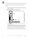
Configuring the Interface Using the Logicmaster 90-30 Configuration Software
To configure the Ethernet Interface, access the I/O Configuration rack screen in the Logicmaster
90-30 Configuration Package, and do the following:
1
.
Move the cursor to the CPU slot (slot1) and press Zoom (F10) to access the CPU
configuration screen.
2
.
If the current CPU is the CPU364, continue to step 3. Otherwise, press CPU (F1) to access
the CPU selection menu. Use the arrow keys to highlight the CPU364 (IC693CPU364),
press Enter to select it, and then press Y to replace the module.
3
.
The initial configuration screen contains the actual CPU configuration parameters. Press
Page Down to access the configuration screens for the Ethernet Interface (Ethernet
parameters and RS-232 serial port parameters).
4
.
Configure the Ethernet parameters. Refer to the topic “Configuration Parameters” that
follows for more information on these fields.
5
.
Optionally, after you have assigned the Ethernet parameters, press Page Down to display the
serial port parameters. You can then change the default settings of the serial ports (optional).
Refer to the topic “Configuration Parameters” that follows for more information on these
fields. We recommend leaving the serial port parameters at default settings.
6
.
After you have completed the configuration, press the Escape key to return to the rack
display. Press Escape again to save the configuration to disk.
7
.
Store the configuration to the PLC so these settings can take effect.
Refer to GFK-0466,
Logicmaster 90 Series 90-30/20/Micro Programming Software User’s
Manual
for more information on configuring the Ethernet Interface using Logicmaster 90-30
software.
CPU364 Configuration Parameters
Ethernet Parameters
Configuration Mode:
This is fixed as TCP/IP.
Adapter Name:
A symbolic name representation of the associated IP address. The character set
is listed in Chapter 6, “Network Administration Support”. The Adapter Name is associated with
the IP address used in Ethernet Global Data. If supported in the PLC programming software,
view all adapter names in Hardware Configuration by going to the Edit menu, choosing Rack
Operations, and selecting Name Resolution. Adapter names are listed in the Adapter Names tab.
Status Address:
The Status Reference Type is the location of the LAN Interface Status (LIS)
bits (16 bits) and the Channel Status bits (64 bits). The Channel Status bits are always located
immediately following the LAN Interface Status bits. The Status address can be assigned to %I,
%Q, %R, %AI or %AQ memory. The default value is the next available %I address.
Note
Do not use the 80-bits assigned to the LIS bits and Channel Status bits for other
purposes or your data will be overwritten.