


4-14 TCP/IP Ethernet Communications for the Series 90™ PLC User's Manual
–
May 2002 GFK-1541B
4
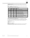
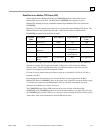
Command 3003, Example 2
Read nine (9) Input Discretesfrom Address 10005 in the remote Modbus/TCP server. Store the
registers at location %T3(bit mode). Return the COMMREQ Status word to %R10.
Dec (Hex)
Word 1
00008 (0008) Length of Channel command Data Block (8–14 words)
Word 2 00000 (0000) Always 0 (no-wait mode request)
Word 3 00008 (0008) Memory type of CRS word (%R)
Word 4 00009 (0009) CRS word address minus 1 (%R10) *
Word 5 00000 (0000) Reserved
Word 6 00000 (0000) Reserved
Word 7 03003 (0BBB) Read from a Modbus/TCP Device
Word 8 00006 (0006) Channel number (6)
Word 9 00002 (0002) Modbus Function Code
Word 10 00074 (004A) Local PLC Memory Type
Word 11 00003 (0003) Local PLC Starting Address
Word 12 00005 (0005) Address in the Remote Device
Word 13 00009 (0009) Number of Input Discretes to Read from the Remote Device
Word 14 00001 (0001) Unit Identifier
* Word 4 (CRS word address) is the only zero-based address in the Command Block. Only this
value requires subtracting 1 from the intended address.
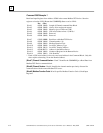
(Word 7) Channel Command Number:
Word 7 identifies the COMMREQ as a Read Data from
Modbus/TCP Device command block.
(Word 8) Channel Number:
Word 8 identifies the channel number previously allocated for
communication with the remote Modbus/TCP server.
(Word 9) Modbus Function Code:
Word 9 specifies Modbus Function Code 2, Read Input
Status.
(Word 10) Local PLC Memory Type:
Words 10-11 specify the location in the local PLC where
the Ethernet Interface will store data received from the remote device . Valid values for Word 10
are listed on page 4-14.
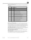
(Word 11) Local PLC Memory Address:
Word 11 determines the starting address in the local
PLC in which the data from the remote device is to be stored. The value entered is the offset (1-
based) from the beginning of PLC memory for the memory type and mode specified in Word 10.
This offset will be either in bits, bytes, or words depending on the mode specified. Valid ranges
of values depend on the PLC’s memory ranges. The user is responsible for assuring that this area
is large enough to contain the requested data without overwriting other application data.
(Word 12) Remote Device Address:
Word 12 specifies the address in the remote Modbus/TCP
device.
(Word 13) Number Registers in Remote Device:
Words 13 specifies the quantity of input
discretes to read from the remote device.
(Word 14) Unit Identifier:
Default is 1. This field is typically used by Ethernet to Serial bridges to
specify the address of a Modbus Slave on a multidrop link. The Modbus/TCP Unit Identifier is a
special control code used in a Modbus/TCP message block. This value is 1 for most Modbus/TCP
messages.