


GFK-1541B Chapter 2 Installation 2-7
2
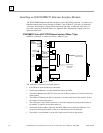
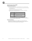
CMM321 Installation
Use the following instructions as a guide when inserting a module into a slot in a baseplate.
These instructions assume that the power supply on the baseplate is to your left.
Warning
Do not insert or remove modules with power applied. This could cause the
PLC to Stop, damage the module, or result in personal injury.
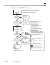
1.
Be sure the Series 90-30 PLC baseplate power is OFF.
2.
Align the module with the desired base slot and connector. Tilt the module upwards so that
the top rear hook of the module engages the slot on baseplate.
3.
Swing the module downward until the connectors mate and the lock-lever on the bottom of
the module snaps into place engaging the baseplate notch.
4.
Visually inspect the module to be sure that it is properly seated.
5.
Connect the cable using one of the two following methods:
•
If using a 10Base-T connection, plug the cable into the 10Base-T port on the front of the
module.
•
If using the AAUI connection, connect the transceiver cable into the 14-pin AAUI port
on the bottom of the module, secure the cable, and connect the other end of the cable to
an external IEEE 802.3 compatible transceiver that is attached to the Ethernet network.
SQE must be enabled on the transceiver. (Note: The transceiver cable may be either
built-in to the transceiver or removable.)
Caution
Do not connect or disconnect a transceiver cable to the AAUI port while
power is applied to the PLC. This may blow the AAUI port fuse and/or
cause permanent damage to the Ethernet Interface.
6.
Use the PLC programming software or a Hand Held Programmer to make sure the PLC CPU
is in Stop mode.