


B-4 TCP/IP Ethernet Communications for the Series 90™ PLC User's Manual
–
May 2002 GFK-1541B
B
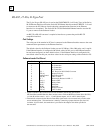
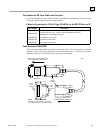
RS-485, 15-Pin, D-Type Port
The 15-pin, D-type, RS-485 port is used on the IC693CMM321 (AAUI-only Type) of the Series
90-30 Ethernet Interface and on the Series 90-70 Ethernet Interface module CMM742. It is used
to connect to the PC Software Loader when the communications firmware in the Ethernet
Interface is to be updated. The Series 90-30 CPU364 Embedded Ethernet Interface uses the RJ-
11 port to connect to the Software Loader.
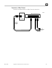
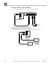
An RS-232 to RS-485 converter is required to interface to systems that provide RS-232
compatible interfaces.
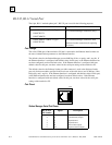
Port Settings
The serial port of the terminal or PC that is connected to the Ethernet Interface must use the same
communications parameters as the Ethernet Interface.
The default values for the Software Loader port are 19,200 bps, 8 bits, Odd parity, and 1 stop bit.
If the Ethernet Interface is configured with default values for this port, or the Ethernet Interface
has not been configured, use these default values. If the Ethernet Interface is configured with
non-default values for this port, use those values for the serial port settings of the terminal or PC.
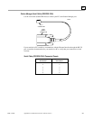
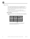
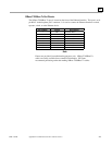
Software Loader Port Pinout
Pin Number
Signal Name Description
1
2
3
4
Shield
No Connection
No Connection
No Connection
5
6
7
8
+5V *
RTS (A)
Signal Ground
CTS (B’)
+5V Power for RS-232/485 Converter
Request To Send
Signal Ground, 0V
Clear To Send
9
10
11
12
RT *
RD (A’)
RD (B’)
SD (A)
Terminating Resistor for RD **
Receive Data
Receive Data
Send Data
13
14
15
SD (B)
RTS (B)
CTS (A’)
Send Data
Request To Send
Clear To Send
* Signals available at the Connector but are not included in the RS-485 specification.
SD (Send Data) and RD (Receive Data) are the same as TxD and RXD (used in the Series Six PLC).
(A) and (B) are the same as - and + . A and B denote outputs, and A’ and B’ denote inputs.
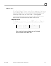
**Termination resistance for the Receive Data (RD) signal needs to be connected only on units at the
end of multidrop lines. This termination is made by connecting a jumper between pins 9 and 10
inside the 15-pin D-shell; the termination is provided in the adapters and cables specified in
the next table.