


3-6 TCP/IP Ethernet Communications for the Series 90™ PLC User's Manual
–
May 2002 GFK-1541B
3
COMMREQ Function Block and Command Block
This section describes the programming structures common to all Communications Requests: the
COMMREQ Function Block and the Command Block.
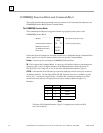
The COMMREQ Function Block
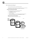
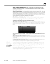
The Communications Request is triggered when the logic program passes power to the
COMMREQ Function Block.
(Enable )
-------------
(Command Block address)
(Rack/Slot Location of
the Ethernet Interface)
(Task value)
-
-
-
-
Function Faulted (logic)
-
OK (Series 90-70 PLCs only)
COMM
REQ
IN
FT
SYSID
TASK
Each of the inputs and outputs are discussed in detail below. Remember that the Command Block
address points to a location in memory that has been set up as the Command Block.
Enable:
Control logic for activating the COMMREQ Function Block.
IN:
The location of the Command Block. It can be any valid address within a word-oriented area
of memory (%R, %AI, or %AQ for the Series 90-30 Ethernet Interface and the Series 90-30
CPU364) (%R, %AI, %AQ, %P, or %L for the Series 90-70 Ethernet Interface (Type 2)).
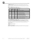
SYSID:
A hexadecimal word value that gives the rack (high byte) and slot (low byte) location of
the Ethernet Interface. For the Series 90-30 CPU364, this must always be set to 0001 to specify
rack 0, slot 1. Note that if using GE Fanuc’s VersaPro PLC software, the leading zeros in this
hexadecimal word value are not displayed on-screen; for example, 0004 will appear as 4.
Examples:
Rack Slot
Hex Word Value
0 4 0004H
34
0304H
29
0209H
4 2 0402H
Note
The Series 90-70 Ethernet Interface (Type 2) is supported only in the main PLC
rack (rack number 0).