


2-30 TCP/IP Ethernet Communications for the Series 90™ PLC User's Manual
–
May 2002 GFK-1541B
2
Installing an IC693 CPU374 with Embedded TCP/IP Ethernet
Interface
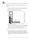
The CPU374 with Embedded Ethernet Interface is mounted on the Series 90-30 PLC baseplate. It
is connected to an Ethernet network via either or both of its auto-sensing 10Base-T/ 100Base TX
ports.
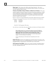
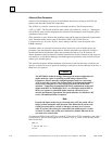
IC693CPU374 Series 90-30 CPU Module with Ethernet Interface
CPU374
EOK
LAN
PS
PORT
STAT
ETHERNET
RESTART
ON
OFF
FRAME
STATION
MGR
LINK/ACT
DEFAULT
STATION
ADDRESS
LABEL
SERIAL
NUMBER
LABEL
100Mbps
PORT 2
LINK/ACT
100Mbps
PORT 1
10/100 ETHERNET
10/100 ETHERNET
The Series 90-30 CPU374 has several user-accessible elements (only the Ethernet Interface’s
applicable elements are discussed here.)
Three Ethernet LEDs are located at the top left of the module. The Ethernet Restart pushbutton is
located below the LEDs. The RS-232 serial port with the RJ-11 connector (similar to a modular
telephone connector) is used to connect to Station Manager. Below the serial port are twoRJ-45
ports, either or both of which can be used to connect to the Ethernet network..
The default station address (MAC address) label is located on the outside of the module.
LEDs
There are eight LEDs on the CPU374. Four of these LEDs: EOK, LAN, STAT, and PS PORT
give module status information. Four LEDS are associated with the two RJ-45 ports. The PS
(Power Supply) PORT LED is not Ethernet related; it indicates the presence of serial traffic
through the serial port of the PLC’s power supply. Each of the three Ethernet LEDs (EOK, LAN,
and STAT) can be ON, OFF, BLINKING slow, or BLINKING fast. They indicate the state of the
Ethernet Interface, traffic at the Ethernet Interface (LAN LED), and that an exception event has
occurred.