


B-20 TCP/IP Ethernet Communications for the Series 90™ PLC User's Manual
–
May 2002 GFK-1541B
B
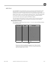
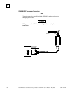
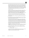
AUI (Transceiver Cable) Connection
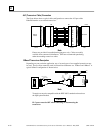
The figure below shows a typical cable configuration to connect the AUI port of the
Ethernet Interface to an external transceiver.
a44668c
Ethernet
Interface
PIN
15- Pin
Male
Transceiver
PIN
15- Pin
Male
15- Pin
Female
SHELL
15- Pin
Female
1
2
3
4
5
6
7
8
9
10
11
12
13
14
15
1
2
3
4
5
6
7
8
9
10
11
12
13
14
15
GND
CP+
TX+
GND
RX+
GND
GND
CP-
TX-
GND
RX-
+12V
GND
SHELL
Note
Pinouts are provided for troubleshooting purposes only. Cables are readily
available from commercial distributors. GE Fanuc recommends purchasing
rather than making transceiver cables.
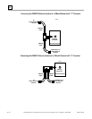
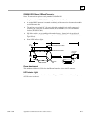
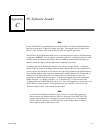
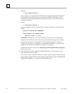
10Base2 Transceiver Description
Depending on your particular application, any of several types of user-supplied transceivers may
be used. The two most commonly used in industrial environments are: 10Base5 and 10Base2. A
typical 10Base2 configuration is shown below.
Transceiver Cable to
Ethernet Interface
15-Pin
Female
Connector
PWR
SQE
XMT
RCV
CP
a44666
15-Pin
Male
Connector
10Base2
Coaxial
Cable
BNC
Connector
BNC
"T"
SQE
must be
ON
.
NOTE
Ethernet Interface
AUI
Terminator or to
other devices
Note
Transceivers must be compatible with the IEEE 802.3 standard and must have
the SQE option Enabled.
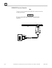
Caution
PLC power must be OFF when connecting or disconnecting the
transceiver.