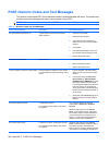
31
32
33
34
36
36
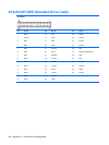
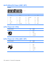
PETn0
SMB_DATA
PETp0
GND
GND
USB_D-
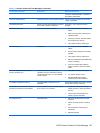
37
38
39
40
41
42
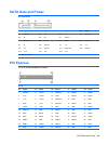
Reserved*
USB_D+
Reserved*
GND
Reserved*
LED_WWAN#
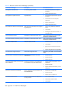
43
44
45
46
47
48
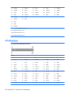
Reserved*
LED_WLAN#
Reserved*
LED_WPAN#
Reserved*
+1.5V
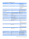
49
50
51
52
Reserved*
GND
Reserved*
+3.3V
NOTE: *Reserved for future second PCI Express LAN (if needed)
**Reserved for future wireless coexistence control interface (if needed)
***Reserved for future UIM interface (if needed)
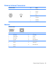
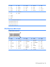
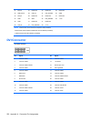
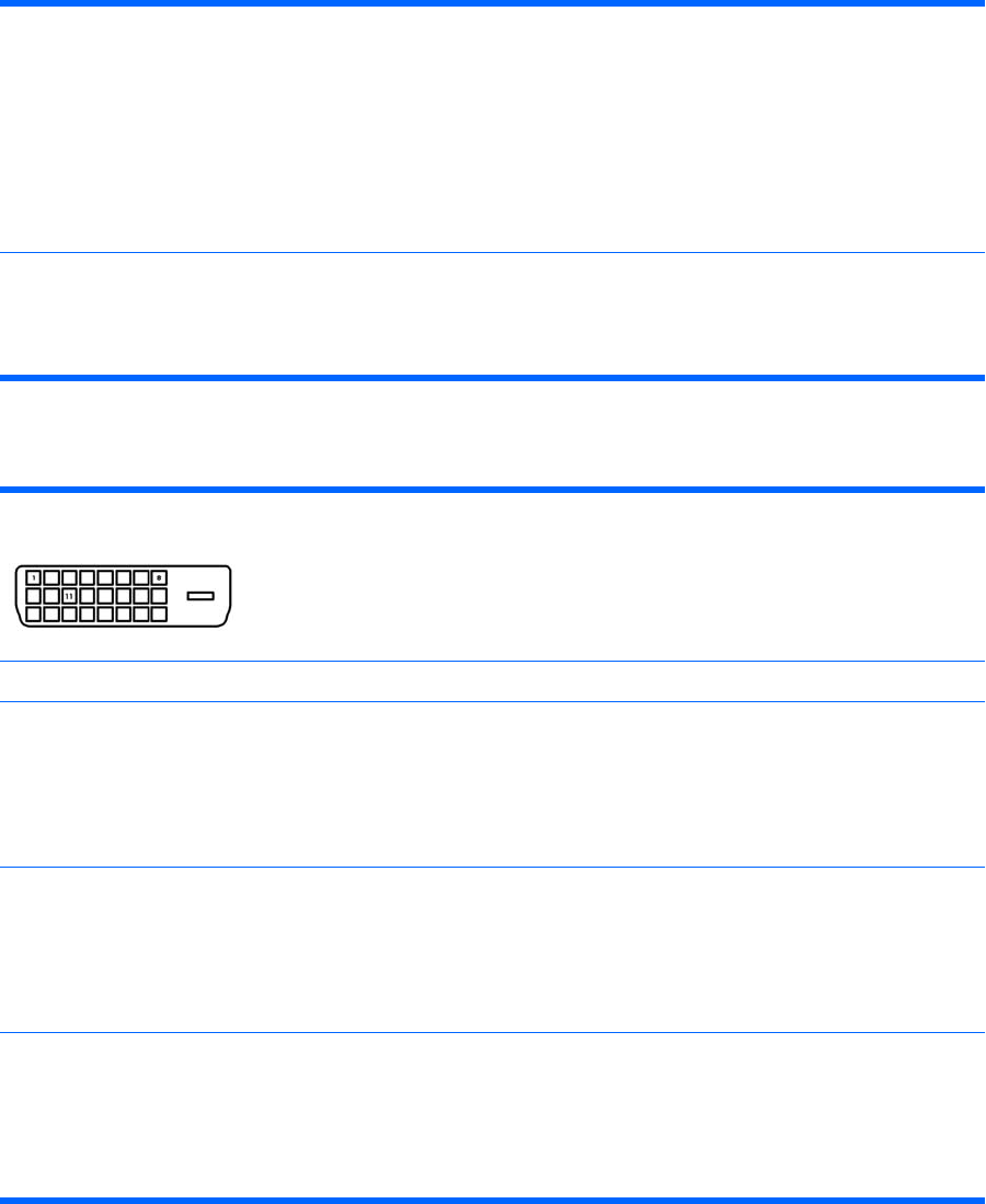
DVI Connector
Connector and Icon
Pin Signal Pin Signal
1
2
3
4
T.M.D.S. Data2–
T.M.D.S. Data2+
T.M.D.S. Data2/4 Shield
T.M.D.S. Data4–
13
14
15
16
T.M.D.S. Data3+
+5V Power
Ground (for +5V)
Hot Pug Detect
5
6
7
8
T.M.D.S. Data4+
DDC Clock
DDC Data
No Connect
17
18
19
20
T.M.D.S. Data0–
T.M.D.S. Data0+
T.M.D.S. Data0/5 Shield
T.M.D.S. Data5–
9
10
11
12
T.M.D.S. Data1–
T.M.D.S. Data1+
T.M.D.S. Data1/3 Shield
T.M.D.S. Data3–
21
22
23
24
T.M.D.S. Data5+
T.M.D.S. Data Shield
T.M.D.S. Clock+
T.M.D.S. Clock-
202 Appendix A Connector Pin Assignments


