


TM 11-6625-2958-14&P
SECTION Ill
OPERATING INSTRUCTIONS
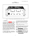
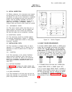
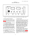
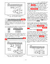
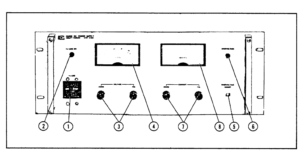
Figure 3-1. Front Panel Controls and Indicators,’ Modal 6259B, 6260B, 6261B, 6268B or 6269B
3-1 TURN-ON CHECKOUT PROCEDURE
3-3 OPERATING MODES
3-2 The following checkout procedure describes
the use of the front panal controls and indicators
(Figure 3-1) and ensures that the supply is opera-
tional.
a. Set LINE circuit breaker ① to ON, and
observe that pilot light ② lights.
b. Adjust VOLTAGE controls ③ until desired
voltage is indicated on voltmeter ④ .
c. To ensure that overvoltage crowbar cir-
cuit is operational, rotate OVERVOLTAGE ADJUST
control ⑤ (screwdriver adjust) counterclockwise
until unit crowbars.
Overvoltage lamp ⑥ will
light and output voltage will fall to zero volts.
d. To deactivate crowbar, return OVERVOLT-
AGE ADJUST control to its maximum clockwise po-
sition and turn off supply. Turn supply back on
and voltage should again be value obtained in step
(b).
e. To check out constant current circuit,
turn off supply. Short circuit rear output terminals
and turn on supply.
f. Adjust CURRENT controls ⑦ until desired
output current is indicated on ammeter ⑧ .
g. Remove short circuit and read following
paragraphs before connecting actual load to supply.
3-4 The power supply is designed so that its mode
of operation can be selected by making strapping
connections between particular terminals on the ter-
minal strip at the rear of the power supply. The ter-
minal designations are stenciled in white on the
power supply below their respective terminals. The
following paragraphs describe the procedures for
utilizing the various operational capabilities of the
power supply. A more theoretical description con-
cerning the operational features of this supply is
contained in Application Note 90, Power Supply
Handbook (available at no charge from your local
Hewlett-Packard sales office). Sales office ad-
dresses appear at the rear of the manual.
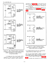
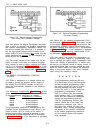
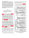
3-5 NORMAL OPERATING MODE
3-6 The power supply is normally shipped with
its rear terminal strapping connections arranged for
constant voltage/constant current, local sensing,
local programming, single unit mode of operation.
This strapping pattern is illustrated In Figure 3-2.
The operator selects either a constant voltage or a
constant current output using the front panel con-
trols (local programming; no strapping changes are
necessary).
3-1