


TM 11-6625-2958-14&P
exactly maximum rated output voltage.
5-90 CONSTANT CURRENT PROGRAMMING
CURRENT
5-91 Zero Current OutPut. To calibrate the zero
current programming accuracy, proceed as direct-
ed in Paragraphs 5-92, 5-93, 5-94, or 5-95,
whichever applies to your particular instrument.
5-92 Standard instrument with resistance or
unity-gain voltage programming.
a.
Connect test setup shown in Figure 5-8.
b. If unit is to be used in local program-
ming mode, turn CURRENT controls fully counter-
clockwise.
If unit is to be used in remote pro-
gramming mode, connect remote programming setup
(Figure 3-6 or 3-7) and adjust remote resistance or
voltage to zero. (minimum).
c. Connect decade resistance box between
pads of position marked for resistor R117 in “ZERO
ADJUST” section of main circuit board (points “G”
and “H” in Figure 5-10; also see Figure 7-10).
d. Rotate VOLTAGE controls fully clockwise
and turn on supply.
e.
Adjust decade resistance box until dif-
ferential voltmeter reads exactly zero volts.
f. Replace decade resistance box with
fixed, metal film, 1%, 1/4 or 1/8 watt resistor of
same value.
5-93 Standard instrument with non-unity gain
voltage programming.
a.
Perform Steps (a) and (b) in Paragraph
5-92.
b. Solder jumper between “wiper” pad and
“-6.2V” pad of position marked for potentiometer
R116 in “ZERO ADJUST” section of main circuit
board (points “I” and “J” in Figure 5-10; also see
Figure 7-10).
c.
Connect decade resistance box between
pads marked for resistor R115 in “ZERO ADJUST”
section of main circuit board (points “ K“ and “ L“
in Figure 5-1 O; also see Figure 7-10).
d.
Perform Steps (d) through (f) in Paragraph
5-92.
5-94 Option 021 with resistance or unity-gain
voltage programming.
a.
Perform Steps (a) and (b) in Paragraph
5-92.
b. Rotate VOLTAGE controls fully clockwise
and turn on supply.
c.
If reading on differential voltmeter is
not exactly zero volts, adjust potentiometer R119
(labeled “CURRENT ZERO” and accessible through
hole in rear panel) until reading is exactly zero.
5-95 Option 021 with non-unity gain voltage pro-
gramming.
a.
Perform Steps (a) and (b) in Paragraph
5-92.
b. Rotate VOLTAGE controls fully clockwise
and turn on supply.
c. If reading on differential voltmeter is not
exactly zero volts, adjust potentiometer R116 (la-
beled “CURRENT PROG” and accessible through
hole in rear panel) until reading is exactly zero.
5-96 CC Programming Accuracy. To calibrate the
constant current programming current, proceed as
directed in Paragraphs 5-97 or 5-98, whichever
applies to your particular instrument.
5-97 Standard instrument.
a. Connect test setup shown in Figure 5-8.
b, Disconnect strap between terminals A5
and A6 on rear barrier strip.
c.
Connect 0.1%, 1/8 watt resistor of value
shown below between terminals A4 and A6 on rear
barrier strip.
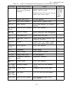
Mode 1
Value
6259B
200
Ω
6260B
200
Ω
6261B
200
Ω
6268B
180
Ω
6269B
200
Ω
d. Connect decade resistance box in place
of R30 (mounted on standoffs on main circuit
board; see Figure 7-1 O).
e.
Rotate VOLTAGE controls fully clockwise
and turn on supply.
f. Adjust decade resistance box until dif-
ferential voltmeter indicates exactly 0.5Vdc.
9.
Replace decade resistance box with
fixed, composition, 5%, 1/2 watt resistor of same
value.
5-98 Option 021.
a.
Perform Steps (a) through (c) in Paragraph
5-97.
b. Rotate VOLTAGE controls fully clockwise
and turn on supply.
c. Adjust potentiometer R116 (labeled “CUR-
RENT PROG” and accessible through hole in rear
panel) until differential voltmeter indicates exactly
0.5Vdc.
5-99 TRANSIENT RECOVERY TIME
5-100 To adjust the transient response, proceed
as follows:
a.
Connect test setup shown in Figure 5-5.
b. Repeat Steps (a) through (k) as outlined
in Paragraph 5-32.
c.
Adjust R47 until transient response is
within specification as shown in Figure 5-6.
5-101 RIPPLE IMBALANCE (50 and 60Hz Operation)
5-102 This procedure ensures balanced operation
of the triac by ensuring that the conduction time
5-20