


TM 11-6625-2958-14&P
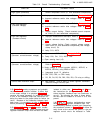
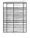
Table 5-3.
Overall Troubleshooting (Continued)
SYMPTOM
PROBABLE CAUSE
High ripple (continued)
current comparator circuit (Z1 and associated components).
Poor line regulation
a.
Improper measurement technique. Refer to Paragraph 5-13.
b. Incorrect reference and/or bias voltages. Refer to Table
5-2.
Poor load regulation
a.
Improper measurement technique. Refer to Paragraph 5-11.
(Constant voltage)
b. Incorrect reference and/or bias voltages. Refer to Table
5-2.
c. Supply current limiting.
Check constant current compara-
tor circuit (Z1 and associated components).
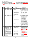
Poor load regulation
a.
Improper measurement technique. Refer to Paragraph 5-44.
(Constant current)
b. Incorrect reference and/or bias voltages. Refer to Table
5-2.
c.
Supply voltage limiting. Check constant voltage compa-
rator circuit (Z1 and associated components) and voltage
clamp circuit, Q1.
d. Leaky C19, A3C3.
Oscillates
a. Adjustment of R47.
Refer to Paragraph 5-99.
(Constant current\constant voltage)
b. Faulty C40, C41, C19, A3C3, R50.
c. Open sensing Iead (+S).
Instability a. Incorrect reference and/or bias voltages; CR92 defective.
(Constant current/constant voltage)
Refer to Table 5-2.
b. Noisy voltage or current controls (A5R121, A5R122, or
A5R123, A5R124); noisy VR60 or VR61.
c.
Integrated circuit Z1 defective.
d. CR4, CR5, CR6, or CR21 leaky.
e.
R2, R3, R4, R5, R6, R22, R30, R31, C2 noisy or drifting.
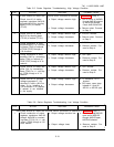
Cannot reach maximum output
a. Q20 shorted.
One or more of series regulator transistors
(A4Q103 through A4Q108) open,
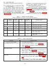
5-58 Table 5-3 contains symptoms and probable
causes of many possible troubles. If either high
or low output voltage is a symptom, Table 5-4
contains the steps necessary to isolate the trouble
to one of the feedback loops and instructions dir-
ecting the tester to the proper table for further iso-
lation.
Because of the interaction between feed-
back loops, it is necessary to refer to Table 5-4
before proceeding to Tables 5-5, 5-6, or 5-7.
isolated to either one.
Tables 5-5 and 5-6 con-
tain instructions for driving each stage of the
series regulator feedback loop into conduction or
cut-off.
By following the steps in these tables,
the fault can be isolated to a circuit or to a com-
ponent.
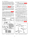
5-60 Table 5-7 contains troubleshooting proce-
dures for the preregulator feedback loop. The
troubleshooting method is based upon comparing
5-59 Tables 5-5, 5-6, and 5-7 contain trouble-
the waveforms shown in Figure 7-9 with those ac-
shooting methods for the series regulator and pre-
tually found at the various test points in the pre-
regulator feedback loops once the fault has been
regulator control circuit. As indicated in Table
5-11