


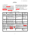
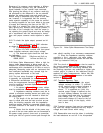
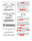
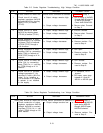
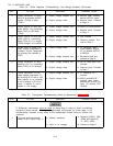
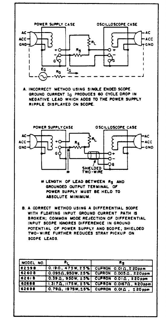
Figure 5-9. Constant Current Ripple and Noise
s -49
Test Setup
of a regulated power supply. AC ripple
and noise current is usually specified
and measured in terms of its RMS
value.
Most of the instructions pertaining to the
ground loop and pickup problem-s associated with
constant voltage ripple and noise measurement
TM 11-6625-2958-14&P
also apply to the measurement of constant current
ripple and noise.
Figure 5-9 illustrates the most
important precautions to be observed when measur-
ing the ripple and noise of a constant current sup-
ply. The presence of a 120Hz waveform on the os-
cilloscope is normally indicative of a correct mea-
surement method. A waveshape having 60Hz as its
fundamental component is typically associated with
an incorrect measurement setup.
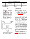
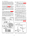
5-50 Ripple and Noise Measurement. To check
the ripple and noise, proceed as follows:
a. Connect oscilloscope or RMS voltmeter
as shown in Figures 5-9A or 5-9B.
b. Turn VOLTAGE controls fully clockwise.
c.
Adjust CURRENT controls until front pan-
e 1 ammeter reads exactly maximum rated output cur-
rent.
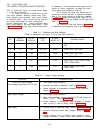
d. The observed ripple and noise should be
less than:
6259B
250µVrms
6260B
250µVrms
6261B
250µVrms
6268B
334µVrms
6269B
250µVrms
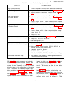
5-51 TROUBLESHOOTING
5-52 Before attempting to troubleshoot this instru-
ment, ensure that the fault is with the instrument
and not with an associated circuit. The perform-
ance test (Paragraph 5-5) enables this to be deter-
mined without having to remove the instrument from
the cabinet.
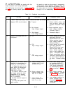
5-53 A good understanding of the principles of op-
eration is a helpful aid in troubleshooting, and it
is recommended that the reader review Section IV
of the manual before attempting to troubleshoot the
unit in detail. Once the principles of operation are
understood, refer to the overall troubleshooting
procedures in Paragraph S-S 6 to locate the symptom
and probable cause.
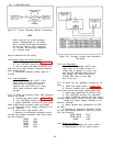
5-54 The schematic diagram at the rear of the
manual (Figure 7-11) contains normal voltage read-
ings taken at various points within the circuits.
These voltages are positioned adjacent to the ap-
plicable test points (identified by encircled num-
bers). The component location diagrams (Figures
7-1 through 7-8, and Figure 7-10) at the rear of the
manual should be consulted to determine the loca-
tion of components and test points.
5-55 If a defective component is located, replace
it and re-conduct the performance test. When a
component is replaced, refer to the repair and re-
placements (Paragraph 5-71) and adjustment and
calibration (Paragraph 5-73) sections of this man-
ual
5-9