


TM 11-6625-2958-14&P
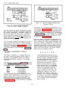
on the maximum voltage rating of the "master" sup-
ply. The value of R
X
is this voltage divided by the
voltage programming current of the slave supply
(1/Kp where K
P is the voltage programming coeffi-
cient). The voltage contribution of the slave is
determined by its voltage control setting.
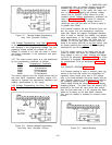
3-53 Overvoltage protection is provided in Auto-
Series operation by connecting the crowbars in par-
allel with correct polarity as in Auto-Parallel oper-
ation (see Paragraph 3-49). The OVERVOLTAGE AD-
JUST potentiometer in each supply should be adjust-
ed so that it trips at a point slightly above the out-
put voltage that the supply will contribute.
3-54 When the center tap of an Auto-Series combi-
nation is grounded, coordinated positive and nega-
tive voltages result. This technique is commonly
referred to as “robber-banding” and an external
reference source may be employed if desired. Any
change of the internal or external reference source
(e.9. drift, ripple) will cause an equal percentage
change in the outputs of both the master and slave
supplies. This feature can be of considerable use
in analog computer and other applications, where
the load requires a positive and a negative power
supply and is less susceptible to an output voltage
change occurring simultaneously in both supplies
than to a change in either supply alone.
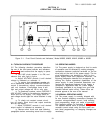
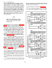
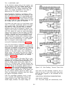
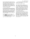
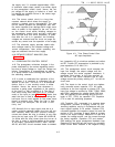
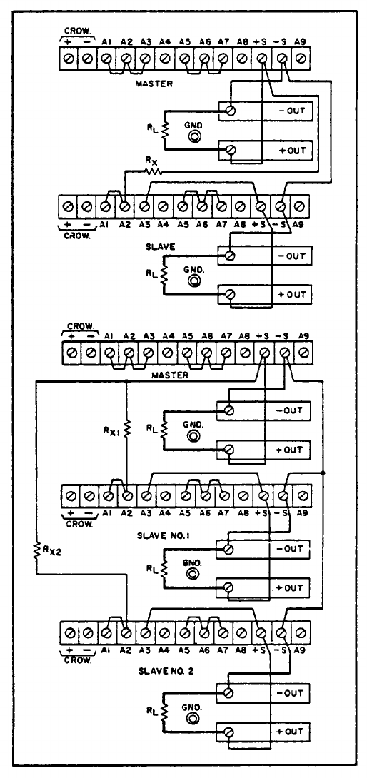
3-55 AUTO-TRACKING OPERATION (Figure 3-12)
3-56 The Auto-Tracking configuration is used when
several different voltages referred to a common bus
must vary in proportion to the setting of a particular
instrument (the control or master). A fraction of the
master’s output voltage is fed to the comparison
amplifier of the slave supply, thus controlling the
slave's output. The master must have the largest
output voltage of any power supply in the group. It
must be the most positive supply in the example
shown on Figure 3-12.
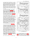
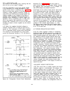
3-57 The output voltage of the slave (Es) is a per-
centage of the master's output voltage (EM), and is
determined by the voltage divider consisting of R
X
and the voltage control of the slave supply, Rp,
where E
S = EM [Rp/(R
x
+Rp)]. Remote sensing and
programming can be used (each supply senses at its
own load), though the strapping patterns given in
Figure 3-12 show only local sensing and program-
ming. In order to maintain the temperature coeffi-
cient and stability specifications of the power sup-
ply, the external resistors should be stable, low
noise, low temperature coefficient (less than 30ppm
per degree Centigrade) resistors.
3-58 The overvoltage protection circuit in each
unit is operable end independently monitors the
voltage across its own load. Notice that if the
master supply crowbars, the output voltage of
Figure 3-12. Auto-Tracking, Tw
O and Three Units
each slave will also decrease. However, the re-
verse is not true. If one of the slave units crow-
bars, the other supplies in *the ensemble will not
be affected.
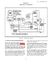
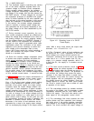
3-59 SPECIAL OPERATING CONSIDERATIONS
3-60 “PULSE LOADING
3-61 The power supply
will automatically cross
3-8