


TM 11-6625-2958-14&P
is equal in either direction (within 25%). To check
for imbalance, proceed as follows:
a.
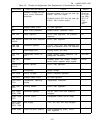
Connect appropriate Ioad resistance
across rear output terminals of supply as follows:
MODEL
Load Resistance
6259B
0.2 Ω 500W, ±5%
6260B
O.1 Ω, 1000W, ±5%
62610
0.4
Ω, 1000W, ±5%
6268B
1.33 Ω, 1200W, ±5%
6269B
0.8 Ω, 2000W, ±5%
b. Connect variable auto transformer be-
tween input power source and power supply power
input; adjust auto transformer for 230Vac input to
supply.
c. Connect oscilloscope (ac coupled) be-
tween TP102 and TP103 (across series regulator).
d. Turn CURRENT controls fully clockwise,
turn on supply, and adjust VOLTAGE controls for
maximum rated output voltage.
e. Adjust oscilloscope to observe 120Hz
sawtooth waveform.
Peak amplitudes of adjacent
sawtooth peaks should be within 25% of each other.
f. If amplitude difference is greater than
25%, turn off supply and replace R82 with decade
resistance.
9.
Turn on supply and adjust decade resist-
ance to reduce imbalance to within 25%.
h. Vary input line voltage from 207 to 253V
ac and insure that imbalance does not exist any-
where within this range.
Replace decade box with
equivalent resistor.
NOTE
If imbalance cannot be reduced to
within 25%, check capacitors C70 and
C72, and diodes CR79 through CR84.
If these components test satisfactori-
ly, the problem may be due to distor-
tion present on the ac power line.
5-103 PREREGULATOR TRACKING (50 and 60Hz
Operation)
5-104 To adjust the voltage drop across the series
regulator, proceed as follows:
a. Connect appropriate load resistance
across rear output terminals of supply as follows:
Model
Load Resistance
62S9B
0.2
Ω
500W, ±5%
6260B
0.1 Ω, 1000W, ±5%
6261B
0.4
Ω, 1000W, ±5%
6268B
1.33
Ω,
1200W, ±5%
6269B
0.8
Ω,
2000W, ±5%
b. Connect variable auto transformer be-
tween input power source and power supply power
input adjust auto transformer for 230Vac input to
supply.
Connect dc voltmeter acress series reg-
ulator (TP102 and TP103).
d. Turn CURRENT controls fully clockwise.
e,
To check voltage drop across regulator
at low output voltage, short circuit load resistor
and adjust VOLTAGE controls for maximum rated
output current on front pane 1 ammeter.
f. Adjust R70 until voltmeter reads 3.5±
0.3Vdc.
g. To check the voltage drop at high output
voltage, remove short circuit from acress load re-
sistor and adjust VOLTAGE controls for maximum
rated output current.
Voltmeter reading should
again be 3.5 ± 0.3Vdc.
h. Vary input line voltage from 207 to 253V
ac. Voltmeter reading should vary between 3.2
(minimum) and 3.8 (maximum) volts. If reading ex-
ceeds this range, proceed with Step (i).
i.
Replace resistor R77 with decade resis-
tance box. Vary input line voltage between 207
and 253Vac while adjusting decade box until volt-
meter reading variation is minimal and within range
of 3.2 to 3.8Vdc.
Rep lace decade box with equiv-
alent resistor.
5-105 50Hz OPERATION (Option 005)
5-106 If the supply is to be operated from a 50Hz
ac input, the following modifications are required:
a. Replace resistor R82 with 240
Ω, ±5%,
1/2 watt resistor, and check ripple imbalance as
described in Steps (a) through (e) of Paragraph
5-101.
b. Perform preregulator tracking adjustment
described in Paragraph 5-103.
5-107 CROWBAR TRIP VOLTAGE
5-108 To adjust A5R125 (OVERVOLTAGE ADJUST),
proceed as follows:
.
Turn screwdriver adjustment, A5R125,
fully clockwise.
b. Turn on supply.
c. Set voltage output to desired trip voltage.
d. Turn A5R125 slowly counterclockwise
until the crowbar is tripped (meter falls to zero
volts).
e. Turn off supply and turn down output
voltage.
f. Turn on supply and set desired operating
output voltage.
NOTE
It is recommended that the crowbar be
set to no less than 5% of the desired
output voltage plus two volts, in or-
der to avoid false tripping of the
crowbar. However, if occasional
crowbar tripping on unloading can be
tolerated, the crowbar trip point can
5-21