


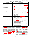

5-33 Temperature Coefficient.
Definition: The change in output volt-
age per degree Centigrade change in
the ambient temperature under condi-
tions of constant input ac line voltage,
output voltage setting, and load re-
sistance.
5-34 The temperature coefficient of a power supply
is measured by placing the power supply in an oven
and varying it over any temperature span within its
rating. (Most HP power supplies are rated for oper-
ation from 0°C to 55°C.) The power supply must be
allowed to thermally stabilize for a sufficient period
of time at each measurement temperature.
5-35 The temperature coefficient given in the spec-
ifications is the maximum temperature-dependent
output voltage change which will result over any one
degree Centigrade interval. The differential volt-
meter or digital voltmeter used to measure the out-
put voltage change of the supply should be placed
outside the oven and should have a long term sta-
bility adequate to insure that its drift will not affect
the overall measurement accuracy.
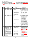
5-36 To check the temperature coefficient, pro-
ceed as follows:
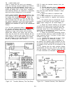
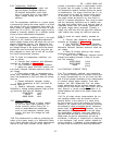
a. Connect load resistance and differential
voltmeter as illustrated in Figure 5-2.
b. Turn CURRENT controls fully clockwise.
c. Adjust front panel VOLTAGE controls until
front panel voltmeter indicates maximum rated out-
put voltage.
d. Place power supply in temperature-con-
trolled oven (differential voltmeter remains outside
oven). Set temperature to 30°C and allow 30 minutes
warm-up.
e. Record differential voltmeter reading.
f. Raise temperature to 40°C and allow 30
minutes warm-up.
g. Observe differential voltmeter reading.
Difference in voltage reading between Step (e) and
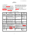
(g) should be less than the following:
62599,62600
12mV
6261B
22mV
6268B, 6269B
42mV
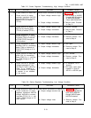
5-37
Qutput Stability.
Definition: The change in output voltage
for the first eight hours following a 30-
minute warm-up period. During the in-
terval of measurement all parameters,
such as load resistance, ambient temp-
erature, and input line voltage are held
constant.
5-38 This measurement is made by monitoring the
output of the power supply on a differential voltme-
ter or digital voltmeter over the stated measurement
interval; a strip chart recorder can be used to
TM 11-6625-2958-14&P
provide a permanent record. A thermometer should
be placed near the supply to verify that the ambi-
ent temperature remains constant during the period
of measurement. The supply should be put in a lo-
cation immune from stray air currents (open doors
or windows, air conditioning vents); if possible,
the supply should be placed in an oven which is
held at a constant temperature. Care must be taken
that the measuring instrument has a stability over
the eight hour interval which is at least an order of
magnitude better than the stability specification of
the power supply being measured. Typically, a
supply may drift Iess over the eight hour measure-
ment interval than during the half-hour warm-up.
5-39 To check the output stability, proceed as
follows :
a. Connect load resistance and differential
voltmeter as illustrated in Figure 5-2.
b. Turn CURRENT controls fully clockwise.
c. Adjust front panel VOLTAGE controls until
differential voltmeter indicates maximum rated out-
put voltage.
d. Allow 30 minutes warm-up, then record
differential voltmeter reading.
e, After 8 hours, differential voltmeter should
change from reading recorded in Step (d) by less
then the following:
6259B, 62600
5.0mV
6261B, 6268B 8.0mV
6269B
14.0mV
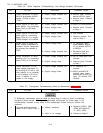
5-40 CONSTANT CURRENT TESTS
5-41 The instruments, methods, and precautions
for the proper measurement of constant current pow-
er supply characteristics are for the most part iden-
tical to those already described for the measurement
of constant voltage power supplies. There are,
however, two main differences: first, the power
supply performance will be checked between short
circuit and full load rather than open
circuit and full
load. Second, a current monitoring resistor is in-
serted between the output of the power supply and
the load.
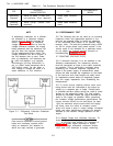
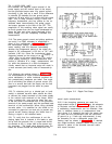
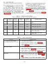
5-42 For all output current measurements the cur-
rent sampling resistor must be treated as a four
terminal device. In the manner of a meter shunt,
the load current is fed to the extremes of the wire
leading to the resistor while the sampling terminals
are located as close as possible to the resistance
portion itself (see Figure 5-7). Generally, any cur-
rent sampling resistor should be of the low noise,
low temperature coefficient (Iess then 30ppm/°C)
type and should be used at no more than 5% of its
rated power so that its temperature rise will be
minimized, If difficulty is experienced in obtaining
a low resistance, high current resistor suitable for
current sampling, a duplicate of the sampling resis-
tor used in this unit (A4R123 or A4R123A-A4R123B)
5-7