


TM 11-6625-2958-14&P
current greater than that available from one supply.
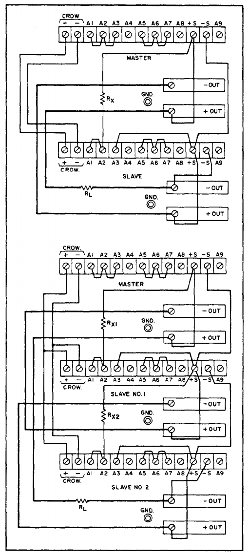
Auto-Parallel operation permits equal current shar-
ing under all load conditions, and allows complete
control of the output current from one master power
supply. The output current of each slave will be
approximately equal to the master’s output current
regardless of the load conditions. Because the
output current controls of each slave are operative,
they should be set to maximum to prevent the slave
reverting to constant current operation; this would
OCCur if the master output current setting exceeded
the slave’s.
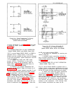
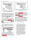
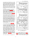
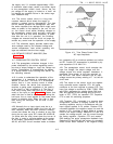
3-48 Additional slave supplies may be added in
parallel with the master/slave combination as
shown in the bottom half of Figure 3-10. All the
connections between the master and slave #1 are
duplicated between slave #1 and the added slave
supply. In addition, the strapping pattern of the
added slave should be the same as slave #1. Re-
mote sensing and programming can be used, though
the strapping arrangements shown in Figure 3-10
show local sensing and programming.
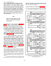
3-49 Overvoltage protection is controlled by the
crowbar circuit in the master supply which monitors
the voltage acress the load and fires the SCR's in
both units if an overvoltage condition occurs. The
firing pulses are fed to the slave supply from trans-
former T90 (winding 5-6) of the master supply
through the “ EXT. CROWBAR TRIGGER
"
terminals on
the rear panel of the master supply. Correct polari-
ty must be observed in connecting the crowbars to-
gether. The overvoltage trip point is adjusted on
the master supply, The OVERVOLTAGE ADJUST po-
tentiometer on the slave supply should be set to
maximum [clockwise) so that the master crowbar
will control the slave.
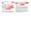
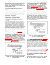
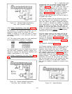
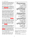
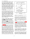
3-50 AUTO-SERIES OPERATION (Figure 3-11)
3-51 Two or more power supplies can be operated
in Auto-Series to obtain a higher voltage than that
available from a single supply. When this connec-
tion is used, the output voltage of each slave sup-
ply varies in accordance with that of the master
supply. At maximum output voltage, the voltage of
the slaves is determined by the setting of the front
panel VOLTAGE controls on the master. The master
supply must be the most positive supply of the
series. The output CURRENT controls of all series
units are operative and the current limit is equal to
the lowest control setting. If any of the output
CURRENT controls are set too low, automatic cross-
over to constant current operation will occur and
the output voltage will drop. Remote sensing and
programming can be used, though the strapping ar-
rangements shown in Figure 3-11 show local sensing
and programming.
3-52 In order to maintain the temperature coeffi-
Figure 3-11.
Auto-Series Operation,
Two and Three Units
cient and stability specifications of the power sup-
ply, the external resistors (Rx) shown in Figure
3-11 should be stable, low noise, low temperature
coefficient (less than 30ppm per degree Centigrade)
resistors.
The value of each resistor is dependent
3-7