


MANUAL CHANGES
Model 6269B DC Power Supply
Manual HP Part No. 06269-90002
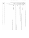
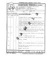
Make all corrections in the manual according to errata below, then check the following table for your power
supply serial number and enter any listed” change(s) in the manual.
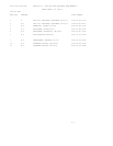
SERIAL
Prefix
ALL
1027A
1027A
1027A
1027A
1027A
1027A
1027A
1027A
1027A
1027A
1436A
1506A
1513A
1535A
Number
0245, 0246,
0255
0236, 0239,
0241 - 0244,
0247, 0248,
0252 -0254,
0256-0305
0306 - 0355
0356 - 0380
0381 - 0429
0430 - 0455
0456 - 0540
0541
- 0870
0871
- 1080
1081
- 1260
1261
- 1470
1471
- 1510
1511
- 1630
1631
- up
MAKE
CHANGES
Errata
1
1,2
1,2,3
1,2, 3,4
1 thru S
1 thru 6
1 thru 7
1 thru 8
1 thru 9
1 thru10
1 thru 11
1 thru 12
1 thru 13
1 thru 14
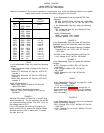
ERRATA:.
In the Replaceable Parts List, make the following
changes:
Knob, front panel, black: Change to HP Part No.
0370-0084.
Option 007: Add knob, HP Part No. 0370-0137,
quantity 1.
Option 008: Add knob, HP Part No. 0370-0137,
quantity 1.
Option 009: Add knob, HP Part No. 0370-0137,
quantity 2.
Under AS-Mechanical:
Bezel, Gray Plastic: Change to HP Part No.
4040-0293 (Black).
Under Chassis Assembly-Mechanical
Bus Bar, C103-C104: Change to HP Part No.
5000-6251.
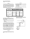
CHANGE 1:
Add new RC network (C2 and R2) on the RFI filter
board assembly A2.
On the schematic, C2 and R2
are connected directly across Triac CR1 (C2 is on
the inboard side of CR1).
C2 and R2 prevent the misfiring (turning on too
soon) of triac CR1 by slowing the rate of voltage
increase across L1A/B (in series with T1) when
the triac turns off.
In the Replaceable Parts list under AZ RFI Filter
Assembly:
C2: Add, 0.047µF, 600V, HP Part No. 0160-0005.
R2: Add, 220
Ω, ±5%, 2W, HP Part No. 0811-1763.
In the Replaceable Parts Iist, make the following
changes:
CR1: Delete Mfr. Part No. and change HP Part
No. to 1884-0209.
Under A2-Mechanical:
Wafer, Insulated, CR1: Delete.
Shoulder Washer, CR1: Delete.
CHANGE 2:
In the Replaceable Parts List under A4 Heat Sink
Assembly and on the Schematic, make the follow-
ing changes:
A4R106 (in the Overvoltage Protection Crowbar):
Change to fxd,
WW, 0.2 Ω, 12W, HP Part No.
0811-3081.
A4Q102 (in the Series Regulator and Driver Cir-
cuit): change to HP Part No. 1854-0458.
CHANGE 3:
In the Replaceable Parts list, make the following
changes:
A1C71: Change to 0.22µF, 80V, HP Part No.
0160-2453.
A1R5: Change to 680 Ω, 5W, HP Part No.
0811-2099.
A1R79: Change to 1.8k, ½W, HP Part No.
0686-1825.
ERRATA :
In the Replaceable Parts List on Page 6-8, under
Chassis-Electrical, change:
C110, C111 to 3000 Vdc.
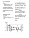
On the schematic, Figure 7-11, connect the +S
output terminal to the A8 terminal on the inboard
side of the + OUT BUS (these terminals are inter-
nally connected).
CHANGE 4:
In the Replaceable Parts List and on the schematic
make the following changes:
A2C1: Change Cl to O.1µF, 400Vdc, HP Part No.
0160-0013.
A1C41: Change C41 to 0.01µF, 200Vdc, HP Part
No. 0160-0161.