


TM 11-6625-2958-14&P
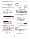
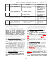
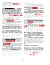
5-7, the circuit is checked by starting with the
the supply in order to gain access to components
output waveform and tracing backwards.
(such as the series regulator transistors) that are
not mounted on the main circuit board. If this is
5-61 Performing the tests given in Table 5-5, 5-6,
the case, refer as necessary to Paragraphs 5-65
and 5-7 will usually require partial disassembly of
through 5-70 for disassembly procedures.
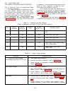
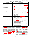
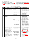
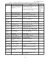
Table 5-4.
Feedback Loop Isolation
STEP
ACTION
RESPONSE
PROBABLE CAUSE
NOTE: After each step, crowbar should be reset by turning supply off and then on.
1
Inspect LINE circuit breaker.
a. Tripped.
a. Check rectifier, filter, and
triac for short. Faulty pre-
regulator. Procceed to Step
3.
b. Not tripped;
b. Series regulator loop in
High voltage output.
high voltage condition.
Proceed to Step 2.
c. Not tripped;
c. Proceed to Step 2.
Low voltage output.
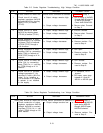
2 Inspect overvoltage lamp on
a.
On.
a.
Check setting of overvolt-
front pane 1.
age adjust (A5R125).
Check A4CR110 for short.
Series regulator loop in
high voltage condition.
Proceed to Step 3.
b. Off;
b. Check setting of overvolt-
High voltage output. age adjust (A5R125).
Check A4CR110 for open,
Q91 for open, Q92 for
short.
Series regulator
loop in high voltage con-
dition. Proceed to Step 3.
c.
off;
c.
Check overvoltage adjust
Low voltage output.
(A5R125). Check A4CR110
for short. Check Q20 for
for short.
Proceed to Step
3.
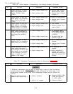
3 Isolate fault to either series
a.
Output voltage normal.
a. Check each series regula-
regulator or preregulator by
Variable from O volts
tor transistor (A4Q103
using the following steps: to about 9 volts. through A4Q108) for open.
(1) Open the gate lead to
Then check preregulator
by disconnecting source
triac A2CR1 by disconnect-
ing either end of resistor
and proceeding to Table
R88 (TP87 or TP88).
5-7.
(2) Place a small dc pow-
b. Output voltage high.
b. High voltage condition in
er supply across the input
Varying controls has
series regulator.
Proceed
capacitors (C 101 through
little or no effect.
to Table 5-5. Leave ex-
C104). A 0-10V, 2A sup
-
ternal source connected.
ply is sufficient.
(3) Set external supply to
c. Low voltage condition in
ten volts.
series regulator loop.
(4) Vary front panel volt-
Proceed to Table 5-6.
age controls.
Leave external source
connected.
5-12
c. Output voltage low,
Varying controls has
little or no effect.