


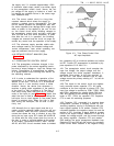
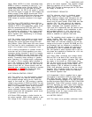
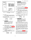
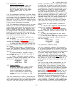
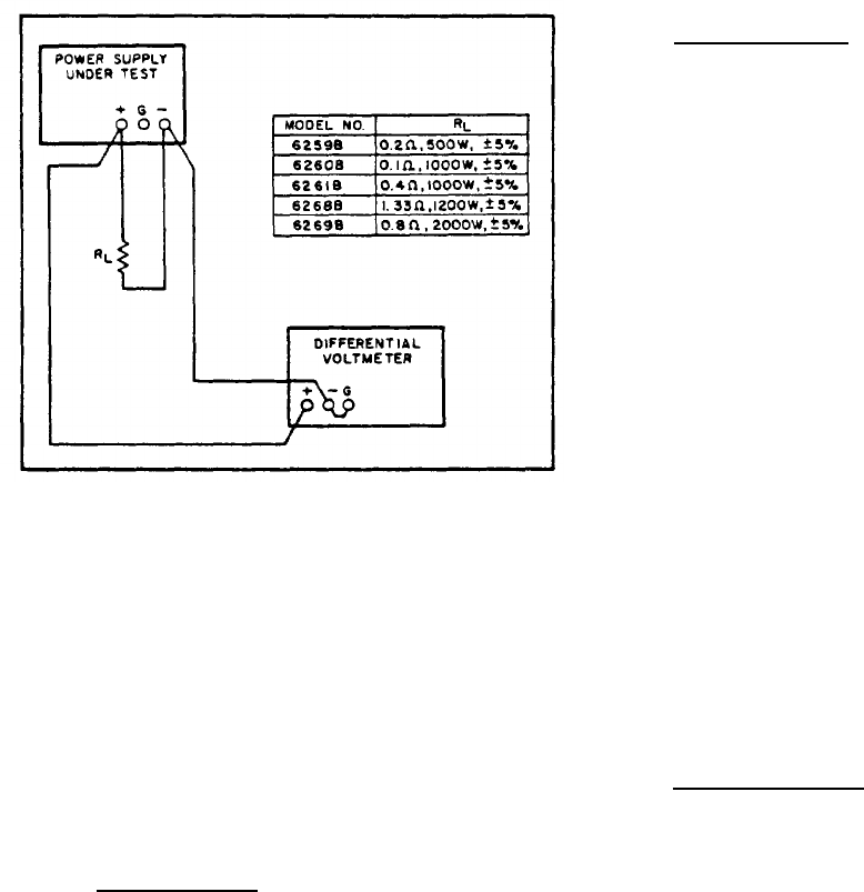
Figure 5-2. Constant Voltage Load Regulation
Test Setup
correct polarity.
c. Turn CURRENT controls fully clockwise.
d. Turn on supply and adjust VOLTAGE con-
trols until front panel meter indicates exactly max-
imum rated output voltage.
e. Differential voltmeter should indicate the
following:
5-11
5-12
tion,
6259B, 6260B
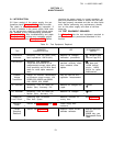
10 ±0.2Vdc
6261B
20 ±0.4Vdc
6268B, 6269B
40 ±0.8Vdc
Load Regulation.
Definition: The change
∆ EOUT in the
static value of dc output voltage re-
sulting from a change in load resist-
ance from open circuit to a value
which yields maximum rated output
current (or vice versa).
To check the constant voltage load regula-
proceed as follows:
‘a. Connect test setup shown in Figure 5-2.
b. Turn CURRENT controls fully clockwise.
c. Turn on supply and adjust VOLTAGE con-
trols until front panel meter indicates exactly max-
imum rated output current.
d. Read and record voltage indicated on dif-
ferential voltmeter.
e. Disconnect load resistor.
f. Reading on differential voltmeter should
not vary from reading recorded in Step (d) by more
than the following:
6259B, 6260B 1.2mV
6261B
2.2mV
6268B, 6269B
4.2mV
5-13
5-14
TM 11-6625-2958-14&P
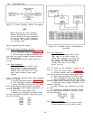
Line Regulation.
Definition: The change
∆ EOUT in the
static value of dc output voltage re-
sulting from a change in ac input volt-
age over the specified range from low
line (usually 207 volts) to high line
(usually 253 volts), or from high
line to low line.
To check the line regulation, proceed as
follows :
a. Connect test setup shown in Figure 5-2.
b. Connect variable auto transformer between
input power source and power supply power input.
c. Adjust variable auto transformer for 207
volts a c input.
d. Turn CURRENT controls fully clockwise.
e. Turn on supply and adjust VOLTAGE con-
trols until front panel meter indicates exactly maxi-
mum rated output voltage.
f. Read and record voltage indicated on dif-
ferential voltmeter.
g. Adjust variable auto transformer for 253V
ac input.
h. Reading on differential voltmeter should
not vary from reading recorded in Step (f) by more
than the following:
5-15
6259B,6260B
1.2mV
6261B
2.2mV
6268B, 6269B 4.2mV
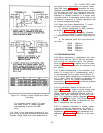
Ripple and Noise.
Definition: The residual ac voltage
superimposed on the dc output of a
regulated power supply. Ripple and
noise may be specified and measured
in terms of its RIMS or (preferably)
peak-to-peak value.
Ripple and noise measurement can be made at any
input ac line voltage combined with any dc output
voltage and load current within the supply's rating.
5-16 The amount of ripple and noise that is pres-
ent in the power supply output is measured either
in terms of the RMS or (preferably) peak-to-peak
value. The peak-to-peak measurement is particu-
larly important for applications where noise spikes
could be detrimental to a sensitive load, such as
logic circuitry. The RMS measurement is not an
ideal representation of the noise, since fairly high
output noise spikes of short duration can be pres-
ent in the ripple without appreciably increasing the
RMS value,
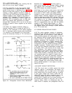
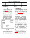
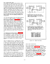
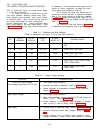
5-17 Ripple Measurements. Figure 5-3A shows an
incorrect method of measuring p-p ripple. Note
that a continuous ground loop exists from the third
wire of the input power cord of the supply to the
third wire of the input power cord of the oscillo-
scope via the grounded power supply case, the
5-3