


Because of its common mode rejection, a differen-
tial oscilloscope displays only the difference in
signal between its two vertical input terminals,
thus ignoring the effects of any common mode sig-
nal produced by the difference in the ac potential
between the power supply case and scope case.
Before using a differential input scope in this man-
ner, however, it is imperative that the common
mode rejection capability of the scope be verified
by shorting together its two input leads at the pow-
er supply and observing the trace on the CRT. If
this trace is a straight line, then the scope is pro-
perly ignoring any common mode signal present. If
this trace is not a straight line, then the scope is
not rejecting the ground signal and must be realign-
ed in accordance with the manufacturer’s instruc-
tions until proper common mode rejection is attain-
ed.
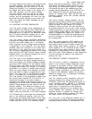
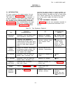
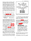
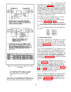
5-23 To check the ripple output, proceed as fol-
lows :
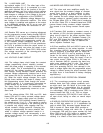
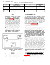
a. Connect oscilloscope or RMS voltmeter
as shown in Figures 5-3A or 5-3B.
b. Turn CURRENT controls fully clockwise.
c. Adjust VOLTAGE controls until front panel
meter indicates maximum rated output voltage.
d. The observed ripple should be less than
the following:
6259B, 6260B, 6261B
500µVrms and 5mV p-p
6268B, 6269B
1mVrms and 5mV p-p
5-24 Noise Spike Measurement. When a high fre-
quency spike measurement is being made, an in-
strument of sufficient bandwidth must be used; an
oscilloscope with a bandwidth of 20 MHz or more is
adequate. Measuring noise with an instrument that
has insufficient bandwidth may conceal high fre-
quency spikes detrimental to the load.
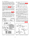
5-25 The test setup illustrated in Figure 5-3A
is generally not acceptable for measuring spikes;
a differential oscilloscope is necessary. Further-
more, the measurement concept of Figure 5-3B
must be modified if accurate spike measurement
is to be achieved
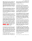
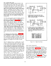
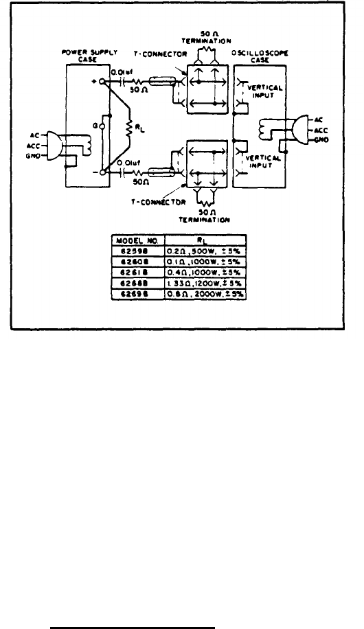
1. As shown in Figure 5-4, tw
O coax cables
must be substituted for the shielded two-wire cable.
2. Impedance matching resistors must be in-
cluded to eliminate standing waves and cable ring-
ing, and capacitors must be inserted to block the
dc current path.
3. The length of the test leads outside the
coax is critical and must be kept as short as pos-
sible; the blocking capacitor and the impedance
matching resistor should be connected directly from
the inner conductor of the cable to the power supply
terminals.
4. Notice that the shields of the power sup-
ply end of the two coax cables are not connected to
the power supply ground, since such a connection
would give rise to a ground current path through the
TM 11-6625-2958-14&P
Figure 5-4. Noise Spike Measurement Test Setup
coax shield, resulting in an erroneous measurement.
5. Since the impedance matching resistors
constitute a 2-to-1 attenuator, the noise spikes
observed on the oscilloscope should be less than
2.5mV p-p instead of 5mV p-p.
5-26 The circuit of Figure 5-4 can also be used for
the normal measurement of low frequency ripple:
simply remove the four terminating resistors and
the blocking capacitors and substitute a higher gain
vertical plug-in in place of the wide-band plug-in
required for spike measurements. Notice that with
these changes, Figure 5-4 becomes a two-cable
version of Figure 5-3B.
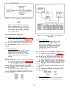
5-27 Transient Recovery Time.
Definition: The time "X" for the output
voltage recovery to within "Y" millivolts
of the nominal output voltage following a
"Z" amp step change in load current,
where: "Y" is specified as 10mV, the
nominal output Voltage is defined as the
dc level ‘halfway between the static out-
put voltage before and after the imposed
load change, and "Z" is the specified
load current change of S amps or the full
load current rating of the supply, which-
ever is less.
5-28 Transient recovery time may be measured at
any input line voltage combined with any output
voltage and load current within rating,
5-29 Reasonable care must be taken in switching
the load resistance on and off. A ha rid-operated
s-s