


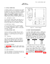
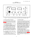
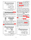
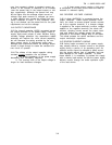
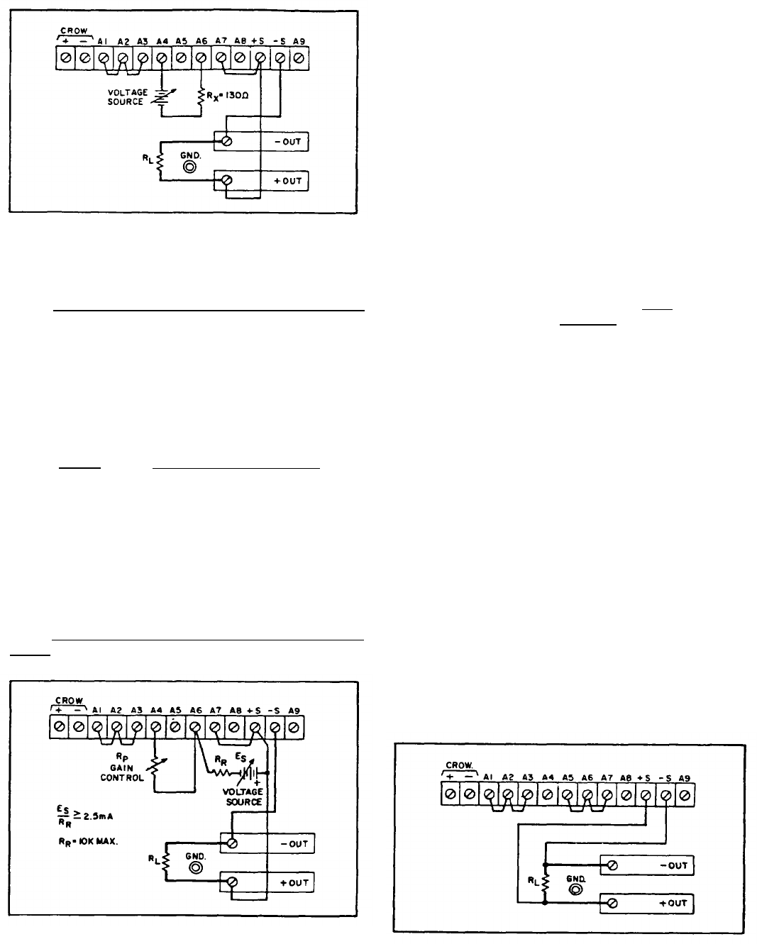
Figure 3-7.
Remote Voltage Programming,
Unity Gain (Constant Current]
3-36 Voltage Programming
, Unity Gain (Figure 3-7).
In this mode, the output current will vary linearly
with changes in the programming voltage. The pro-
gramming voltage should not exceed 0.6 volts.
Voltage in excess of 0.6 volts will result in exces-
sive power dissipation in the instrument and possi-
ble damage.
3-37 The output current varies at a rate determined
by the programming coefficient as follows:
Model
Programming Coefficient
6259B
10.0mV/ampere
6260B
5.0mV/ampere
6261B
10.0mV/ampere
6268B
16.7mV/ampere
6269B
10.0mV/ampere
The current required from the voltage source will be
less than 20µA. Impedance matching resistor R
x
is
required to maintain the temperature coefficient and
stability specifications of the supply.
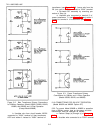
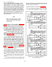
3-38 Voltage Programming,
Non-Unity Gain (Figure
3-8). The power supply output current can be
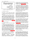
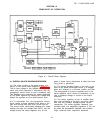
Figure 3-8.
Remote Voltage Programming,
Non-Unity Gain (Constant Current)
TM 11-6625-2958-14&P
programmed using an external voltage source with
variable gain by utilizing the strapping pattern
shown in Figure 3-8. In this mode, the output cur-
rent is found by multiplying the external voltage
source (Es) by [Rp/(RR x Kp)], where Kp is the
constant current voltage programming coefficient as
given in Paragraph 3-37. The value of reference
resistor R
R and programming voltage source E
s
should be such that the value of ES/RR is equal to
or greater than 2.5mA.
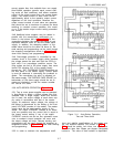
3-39 External resistors Rp and R
R should have sta-
ble, low noise, and low temperature coefficient
(less than 30ppm per degree Centigrade) character-
istics in order to maintain the stability and temper-
ature specifications of the Power supply. Reference
resistor R
R should not exceed 10K. Note that it is
possible to use the front panel current control al-
ready in the supply (A5R123) as the gain
control (Rp)
by simply removing the external Rp and strapping
terminals AS and A6 together.
3-40 The output current of the supply may be ad-
justed to exactly zero when the external program-
ming voltage is zero by either inserting and adjust-
ing R115 as discussed in Paragraph 5-93, or, if the
instrument is equipped with Option 021, by adjust-
ing potentiometer R116 as discussed in Paragraph
5-95.
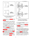
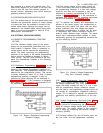
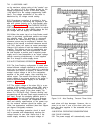
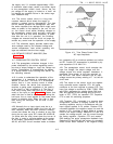
3-41 REMOTE SENSING (Figure 3-9)
3-42 Remote sensing is used to maintain good reg-
ulation at the load and reduce the degradation of
regulation which would occur due to the voltage
drop in the leads between the power supply and the
load. Remote sensing is accomplished by utilizing
the strapping pattern shown in Figure 3-9. The
Power supply should be turned off before changing
strapping paterns. The leads from the sensing (±S)
terminals to the load will carry much less current
than the load leads and it is not required that these
leads be as heavy as the load leads. However,
they must be twisted or shielded to minimize noise
pickup.
Figure 3-9.
Remote Sensing
3-5