


TM 11-6625-2958-14&P
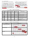
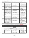
Table 5-6.
Series Regulator Troubleshooting, Low Voltage Condition (Continued)
STEP
ACTION
RESPONSE
PROBABLE CAUSE
2
Check conduction of driver
a. Output voltage remains low. a. A4Q102 open, thermal
A4Q102 by shorting A4Q101 switch A4TS101 open.
emitter (TP100) to base
(TP45).
b. Output voltage rises. b. Remove short. Proceed
to Step 3.
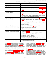
3
Check turn-off of error am-
a, Output voltage remains low.
a. A4Q101 or CR44 shorted.
plifier A4Q10 1 by connecting
base (TP45) to Q42 base
b. Output voltage rises. b. Remove short. Proceed
(TP44).
to Step 4.
4
Check turn-off of error am-
a. Output voltage remains low, a. Q42 shorted.
plifier Q42 by connecting
base (TP44) to +11V supply
b. Output voltage rises. b. Remove resistor. Pro-
(TP66) through a 1K
Ω
resistor.
teed to Step 5.
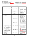
5 Isolate fault to either con- a, Output voltage rises.
a. Z1 defective, open
stant voltage comparator or
strap between A6 and
constant current comparator
A7, or shorted A5R123
by opening the cathode of
or A5R124.
CR20.
b. Output voltage remains low. b. Reconnect lead and
proceed to Step 6.
6 Check conduction of mixer a. Output voltage remains low.
a. Q41 or CR40 open, Q40
amplifier Q41 by connecting
shorted.
base (TP40) to +S terminal.
b. Output voltage rises.
b. Remove short. Proceed
to Step 7.
7
Check conduction of con-
a. Output voltage remains low. a. Z1 defective, R1
stant voltage comparator Z 1
shorted.
by shunting R110 with a 10K
b. Output voltage rises.
ohm resistor, or by installing
b. A5R121 and A5R122
a 10K
Ω resistor in R110 po-
shorted, open strap’
sition if resistor is not in-
between AZ and A3, R5
stalled in the supply.
open, C2 shorted, CR7
shorted.
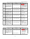
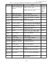
Table 5-7.
Preregulator Troubleshooting (Refer to Waveforms in Figure 7-9)
STEP
ACTION
RESPONSE
PROBABLE CAUSE
A differential oscilloscope must be used for these tests in order to avoid a potentially
dangerous shock hazard.
Floating a single-ended oscilloscope for these tests is not
recommended, because it may result in the oscilloscope chassis being at 230Vac line
potential.
1 Connect oscilloscope be-
a. Normal waveform.
a. Defective A2CR1, R88,
tween TP89 (+) and TP86 (-).
CR88, A2L1A/A2L1B,
T1, A2C1, A2R1.
b. Little or no voltage.
b. Proceed to Step 2.
.
5-14