


TM 11-6625-2958-14&P
ing current to the summing point, ensuring that the
triac will fire at low output “voltages.
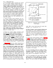
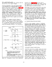
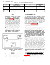
4-24 The summation of the input signals results
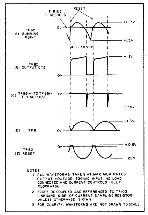
in the generation of a voltage waveform at TP80
similar to that shown in waveform (A) of Figure 4-4.
When the linear ramp portion of the waveform
reaches a certain negative threshold voltage, di-
odes CR74 and CR75 become forward biased. The
negative voltage is then coupled to the base of
transistor Q72. Transistors Q72 and Q73 form a
squaring circuit resembling a Schmitt trigger con-
figuration. Q72 is conducting prior to firing time
due to the positive bias connected to its base
through R84, Transistor Q73 is cut off at this time
because its base is driven negative by the collect-
or of Q72.
4-25 When the negative threshold voltage is
reached, transistor Q72 is turned off and Q73 is
turned on. The conduction of Q73 allows capacitor
C71 to discharge rapidly through pulse transformer
T70 resulting in the generation of a firing pulse
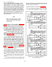
across the secondary winding of T70. As shown in
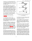
Figure 4-4. Preregulator Control Circuit Waveforms
waveform (C) of Figure 4-4, the firing pulse is
quite narrow because Q73 saturates rapidly, causing
the magnetic field surrounding T70 to collapse. Di-
ode CR76 damps out positive overshoot.
4-26 Reset of the control circuit occurs once every
8.33 milliseconds when the rectified ac voltage at
the junction of CR77, CR78, and CR79 (TP82) in-
creases to a level at which diode CR78 becomes
forward biased. Summing capacitor C70 is then al-
lowed to discharge through CR78. Diodes CR74 and
CR75 become reverse biased at reset and transistor
Q72 reverts to its “on” state. Consequently, Q73
is turned off and capacitor C71 charges up through
R79 at a comparatively slow rate until the collector
voltage of Q73 reaches approximately +11 volts.
The above action causes the small positive spike
that appears across the windings of pulse transform-
er at T70 at reset time.
4-27 SERIES REGULATOR AND DRIVER
4-28 The series regulator consists of transistors
A4Q103 through A4Q108 connected in parallel. The
transistors serve as the series or “pass” element
which provides precise and rapid control of the out-
put. Resistors A4R150 through A4R155 allow high
output currents to be equally shared by the series
regulator transistors. The conduction of the series
transistors is controlled by signals obtained from
driver A4Q102, which is connected in a Darlington
configuration with the parallel-connected series
regulator transistors. Thermal switch A4TS101 opens
if the heat sink assembly temperature exceeds ap-
proximately 230°F, thus turning off the series regu-
lator transistors. This feature protects critical
components of the supply from excessive tempera-
tures which could occur if cooling fan A4B1 failed.
Diode CR50 provides a discharge path for the out-
put capacitors when the supply is rapidly down-
programmed; R57 limits the discharge current flow-
ing through the diode and through error amplifier
A4Q101. Diode A4CR105, connected across the reg-
ulator circuit, protects the series elements from
reverse voltages that could develop across them
during parallel operation if one supply is turned on
before the other.
4-29 SHORT CIRCUIT PROTECTION
4-30 This circuit acts to initially protect the series
regulator against a simultaneous full-voltage, full-
current conditions such as might occur if the output
were shorted when the controls were set to deliver
a high output voltage and current. Under this con-
dition, Q20 goes into heavy conduction due to the
increased voltage across the series regulator,
putting R26 in parallel with the current controls and
thus limiting the current to less than 10% of the
supply’s rating.
Within 10 milliseconds after the
short circuit is imposed, the preregulator shuts off.
4-4