


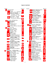
TABLE OF CONTENTS
Section
Page No.
Section
0
INSTRUCTIONS
. . . . . . . . . . . . . . .
6-1
0-1 Scope
0-1
0-2 Indexes of Publications
0-3 Forms and Records
0-1
0-4 Reporting Equipment Im-
provement Recom-
mendations (EIR) 0-1
0-5 Administrative Storage
0-6 Destruction of Army
Electronics Materiel 0-1
I GENERAL INFORMATION. . . . . . . . 1-1
1-1 Description
1-1
1-7 Specifications
1-2
1-9 Options
1-2
1-11 Instrument/Manual
Identification
1-2
1-14 Ordering Additional Manuals 1-3
II INSTALLATION . . . . . . . . 2-1
2-1
2-3
2-5
2-7
2-9
2-11
2-13
2-15
2-17
2-19
2-21
2-23
2-25
2-27
2-29
Initial Inspection
Mechanical Check
Electrical Check
Installation Data
Location
Outline Diagram
Rack Mounting
Input Power Requirements
Connections for 208 Volt
Operation (Model 6259B,
6261B, or 6268B)
Connections for 208 Volt
Operation (Model 6260B
and 6269B)
Connections for 115 Volt
Operation (Model 6259B,
6261B, and 6268B)
Connections for 115 Volt
Operation (Model 6260B)
Connections for 50Hz
Operation
Power Cable
Repackaging for Shipment
2-1
2-1
2-1
2-1
2-1
2-1
2-1
2-1
2-1
2-2
2-3
2-3
2-4
2-4
2-4
III OPERATING INSTRUCTIONS . . . . . . . .3-1
3-1 Turn-On Checkout Procecdure 3-1
3-3 Operating Modes
3-5 Normal Operating Mode
3-7 Constant Voltage
3-9 Constant Current
3-11 Overvoltage Trip
Point Adjustment
3-14 Connecting Load
3-18 No Load Operation
3-20 Operation Beyond
Rated Output
3-1
3-1
3-2
3-2
3-2
3-2
3-2
3-3
3-22
3-23
3-32
3-41
3-46
3-50
3-55
3-59
3-60
3-62
3-65
3-67
Optional Operating Modes
Remote Programming,
Constant Voltage
Remote Programming,
Constant Current
Remote Sensing
Auto-Parallel Operation
Auto-Series Operation
Auto-Tracking Operation
Special Operating
Considerations
Pulse Loading
Output Capacitance
Reverse Voltage Loading
Reverse Current Loading
Page No.
3-3
3-3
3-4
3-5
3-6
3-7
3-8
3-8
3-8
3-9
3-9
3-9
IV PRINCIPLES OF OPERATION.. . . . ...4-1
4-1
4-16
4-17
4-27
4-29
4-31
4-38
4-43
4-46
4-50
4-56
4-59
4-64
4-68
Overall BIock Diagram
Discussion
Detailed Circuit Analysis
Preregulator Control Circuit
Series Regulator and Driver
Short Circuit Protection
Constant Voltage Comparator
Constant Current Comparator
Voltage Clamp Circuit
Mixer and Error Amplifiers
Overvoltage Protection
Crowbar
Turn-On Control Circuit
Reference Regulator
Meter Circuit
Additional Protection Features
4-1
4-3
4-3
4-4
4-4
4-5
4-5
4-6
4-6
4-6
4-7
4-7
4-7
4-8
v
MAINTENANCE . . . . . . . . . . . . . . . . . .. 5-1
5-1
5-3
5-5
5-7
5-40
5-51
5-56
5-62
5-71
5-73
5-75
5-77
5-79
5-81
5-90
.5-99
Introduction
Test Equipment Required
performance Test
Constant Voltage Tests
Constant Current Tests
Troubles hooting
Overall Troubleshooting
Procedure
Disassembly Procedures
Repair and Replacement
Adjustment and Calibration
Meter Zero
Voltmeter Calibration
Ammeter Calibration
Constant Voltage
Programming Current
Constant Current
Programming Current
Transient Recovery Time
5-101 Ripple Imbalance 150 and
60Hz Operation)
iii
5-l
5-1
5-2
5-2
5-7
5-9
5-10
5-15
5-16
5-18
5-18
5-18
5-18
5-19
5-20
5-20
5-20
0-1
0-1