


TM 11-6625-2958-14&P
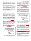
4-6 The feedback signals controlling the conduc-
tion of the series regulator originate within the
constant voltage or constant current comparator.
During constant voltage operation the constant
voltage comparator continuously compares the out-
put voltage of the supply with the drop across the
VOLTAGE controls.
If these voltages are not equal,
the comparator produces an amplified error signal
which is further amplified by the error amplifier and
then fed back to the series regulator in the correct
phase and amplitude to counteract the difference.
In this manner, the constant voltage comparator
helps to maintain a constant output voltage and
also generates the error signals necessary to set
the output voltage at the level established by the
VOLTA GE controls.
4-7 During constant current operation, the con-
stant current comparator detects any difference be-
tween the voltage drop developed by the load cur-
rent flowing through the current sampling resistor
and the voltage acress the CURRENT controls. If
the two inputs to the comparator are momentarily
unequal, an error signal is generated which (after
amplification) alters the conduction of the series
regulator by the amount necessary to reduce the
error voltage at the comparator input to zero.
Hence, the IR drop across the current sampling re-
sistor, and therefore the output current, is main-
tained at a constant value.
4-8 Since the constant voltage comparator tends
to achieve zero output impedance and alters the
output current whenever the load resistance
changes, while the constant current comparator
causes the output impedance to be infinite and
changes the output voltage in response to any load
resistance change, it is obvious that the two com-
parison amplifiers cannot operate simultaneously.
For any-given value of load resistance, the power
supply must act either as a constant voltage source
or as a constant current source - it cannot be both.
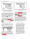
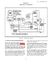
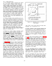
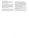
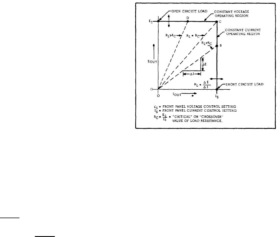
4-9 Figure 4-2 shows the output characteristic of
a constant voltage/constant current power supply.
With no load attached (RL =
∞), IOUT = O, and
E
OUT = Es, the front panel voltage control setting.
When a load resistance is applied to the output
terminals of the power supply, the output current
increases, while the output voltage remains con-
stant; point D thus represents a typical constant
voltage operating point. Further decreases in load
resistance are accompanied by further increases in
I
OUT with no change in the output voltage until the
output current reaches Is, a value equal to the front
panel current control setting. At this point the sup-
ply automatically changes its mode of operation and
becomes a constant current source; still further
decreases in the value of load resistance are ac-
companied by a drop in the supply output voltage
with no accompanying change in the output current
Figure 4-2. Operating Locus of a CV/CC
Power Supply
value. With a short circuit across the output load
terminals, I
OUT = ES and EOUT = O.
4-10 The ‘
:
Crossover” value of load resistance can
be defined as R
C = Es/Is. Adjustment of the front
panel voltage and current controls permits this
“crossover” resistance R
C to be set to any desired
value from 0 to
∞. If RL is greater than RC, the
supply is in constant voltage operation, while if R
L
is less than RC, the supply is in constant current
operation.
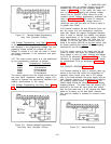
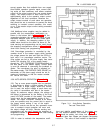
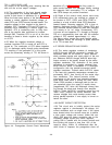
4-11 The short circuit protection circuit (see Fig-
ure 4-1) protects the series regulator in the event
of a shorted output when the controls are set to a
high output voltage and current. The protection cir-
cuit monitors the voltage drop across the series
regulator. If the drop rises above a preset level,
the protection circuit limits the current through the
series regulator until the preregulator can reduce
the voltage across the series regulator. Once this
voltage returns to normal, the short circuit protec-
tion circuit is turned off and has no effect on norm-
al operation of the supply.
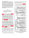
4-12 The overvoltage protect ion crowbar monitors
the output of the supply, and if it exceeds a preset
(adjustable) threshold, fires an SCR which short
circuits the supply.
The circuit also sends a turn-
down signal to the preregulator control circuit.
4-13 The overvoltage limit circuit protects the main
rectifier diodes and filter capacitors from damage
that might occur if the series regulator transistors
were shorted or the voltage programming pot were
opened. The circuit monitors the output voltage of
4-2