


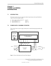
Chapter 7 Power and Signal Distribution
7.3 POWER DISTRIBUTION
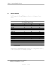
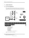
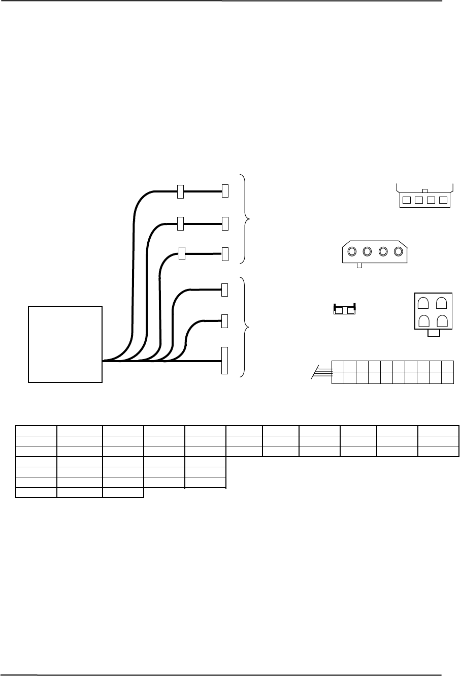
7.3.1 3.3/5/12 VDC DISTRIBUTION
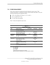
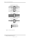
The power supply assembly includes a multi-connector cable assembly that routes DC power to
the system board as well as to the individual drive assemblies. Figure 7-2 shows the power supply
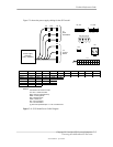
cabling for D315 models while figure 7-3 shows the power supply cabling for the d325 model.
P7, P8
P8
P2
P6
P7
To
Drive
Assemblies
4 3 2 1
P2, P4-6
P4
P5
1 2 3 4
P9
P3
P9
2 1
P3
Power Supply
Assembly
(Assy. #226910)
1
2
4 3
To
System
Board
P1
P1
6
16
5
15
1
11
12
2
3
13
4
14
7
17
8
18
9
19
10
20
n. Pin 4 Pin 6 Pin 10
Con Pin 1 Pin 2 Pin 3 Pin 5 Pin 7 Pin 8 Pin 9
P1 +3.3 +3.3 RTN +5 RTN +5 RTN POK +5 Aux +12
P1 [1] +3.3 -12 RTN
P2, +12 GND GND +5
P3 ND GND +12.8 +12.8
P7, +5 GND
PS On
4-6
G
8
RTN RTN RTN NC +5 +5
GND +12
FC P9 FS
NOTES:
le.
round)
e
cted
[1] This row represents pins 11 - 20 of connector P1
igure 7-2. D315 Model Power Cable Diagram
Connectors not shown to sca
All + and - values are VDC
.
RTN = Return (signal g
GND = Power ground
RS = Remote sens
POK = Power OK
NC = Not conne
FS = Fan Sink
FC = Fan Command
F
Compaq D315 and hp d325 Personal Computers
Featuring the AMD Athlon XP Processor
Second Edition - April 2003
7-6