


Chapter 4 System Support
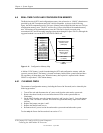
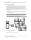
4.7.4.1 Cooling for D315 Models
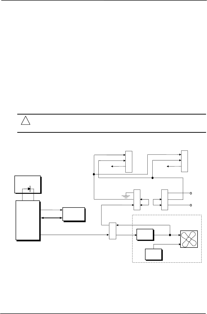
The temperature controller produces the Fan CMD (which varies from 0 to +2.5 VDC) that is
applied to the speed control circuitry of the power supply assembly. The output of the speed
control circuitry controls the power supply assembly’s internal fan and is also routed back to the
system board and, in the default jumper configuration, is applied as the Fan Sink signal to the
negative terminal of the connected fans. The default jumper configuration also applies + 5 VDC to
the positive terminal of the fans. With the Fan CMD signal being varied from +0.5 to -7 VDC, the
chassis and CPU fans will be driven by a voltage from about +5 to +12 VDC, depending on the
processor temperature.
In a characteristically warm environment or should the speed regulation circuitry be inadequate or
fail it may be desirable to have the fans driven by a constant +12 VDC by configuring both
FAN_SEL jumpers to pins 1 and 2.
Note that the power supply assembly fan operates independently of the CPU and chassis fans.
CAUTION: Both FAN_SELn jumpers must have the same configuration (jumpers on
the same pins). Different jumper settings (one jumper on pins 1 and 2 and the other
jumper on pins 2 and 3) may result in equipment damage.
NOTES: Jumpers shown in standard configuration.
Fan Pwr
+5 VDC
PS Fan
(-)
(+)
PS
Circuits
Speed
Control
Power Supply Assembly
1
2
Fan
Sink
Fan
CMD
PWR_FAN
Header
Fan Sink
Fan Pwr
NC
TACH
NC
TACH
2
3
(-)
CPU Fan
Header
1
(+)
2
3
(-)
Chassis Fan
Header
1
(+)
Fan CMD
+5 VDC
1
2
3
FAN_SEL2
Header/Jum
p
er
1
2
3
FAN_SEL1
Header/Jumper
SMBus
Super
I/O Cntlr.
Therm-
+12 VDC
AMD1030
Temp.
Controller
Processor
TACH function of the fan(s) not used.
Figure 4-12. D315 Model Fan Control Block Diagram
Compaq D315 and hp d325 Personal Computers
Featuring the AMD Athlon XP Processor
Second Edition – April 2003
4-28