


Technical Reference Guide
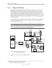
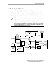
4.7.4.2 Cooling for d325 Models
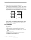
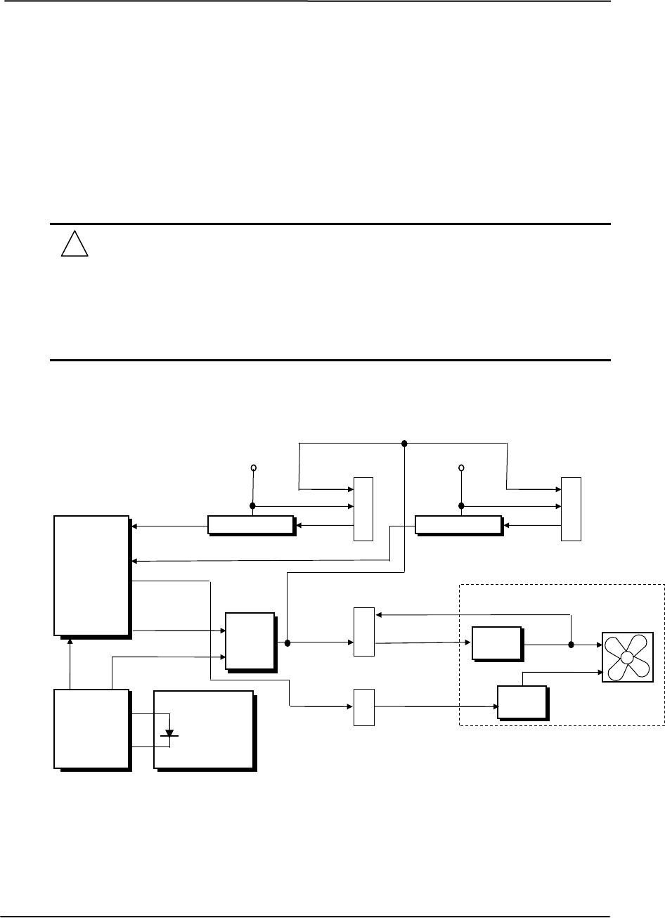
The fan control logic on the d325 model differs from the D315 system in that fans are controlled
by the system board logic. The fans are driven by a constant positive 12 volts on one side and a
negative voltage that is variable through the Fan Cntrl logic. A Hardware Monitor ASIC monitors
the temperature of the processor and changes the duty cycle of the Fan PWM to increase or
decrease fan speed based on the processor temperature. The Fan Clamp signal is initiated by the
BIOS and produced by the GPIO at boot time to ensure that the fans start at boot time.
NOTE: A protection mechanism is provided where the processor threshold
temperature programmed into the Hardware Monitor ASIC is temporarily set by the
BIOS to a lower than normal level during the initial start up to protect against the
possibility of an incorrectly installed heat sink. If during the boot period the processor’s
temperature reaches 100° C the hardware Monitor will assert the Therm signal causing
the I/O Controller to de-assert the PS On signal, which will shut down the power supply.
If the processor does not reach 100° C during the boot sequence the BIOS then re-sets
the thermal threshold to the run-time level of 125° C
Therm
PS On
ATX Power
P1
14
PS On
Fan PWM
Hardware
Monitor
ASIC
Processor
+5 VDC
PS Fan
(-)
(+)
PS
Circuits
Speed
Control
Power Supply Assembly
Sense
Chassis
Fan Tach
Tach Logic
+12 VDC
2
3
(-)
Chassis Fan
Header P8
1
(+)
1
2
Header
P16
Fan
C
Tach Logic
+12 VDC
2
3
(-)
CPU Fan
Header P70
1
(+)
Fan Sink
Fan
Cntrl
CPU
Fan Tach
Fan
Clamp
Sense
LPC47B367
I/O
Controller
Figure 4-13. d325 Model Fan Control Functional Block Diagram
Compaq D315 and hp d325 Personal Computers
Featuring the AMD Athlon XP Processor
Second Edition - April 2003
4-29